产品支持与文档
- 1: SWITNEX AC85-250V Universal Wireless Remote Control Switch User Manual
- 2: SWITNEX Tuya WiFi RF Garage Controller User Manual
- 3: SITNEX Waterproof Wireless Remote Control Switch (AC 85V-250V, 30A) User Manual
- 4: SWITNEX Mini Wireless WiFi Switch User Manual
- 5: SWITNEX Kinetic Wireless Light Switch and 10A Relay Receiver Kit User Manual
- 6: SWITNEX 4 Channels Wireless Relay Remote Control Switch User Manual
- 7: SWITNEX 4-Channel Wireless Relay Remote Control Switch User Manual
- 8: SWITNEX Waterproof Wireless Remote Control DC 8V-80V 30A Radio Control Switch User Manual
- 9: SWITNEX Smart WiFi Relay Module 1CHx4-TEW User Manual
- 10: SWITNEX Smart WiFi 2-Channel Relay Module with Bluetooth Transmitter User Manual
- 11: SWITNEX EW-4CH 4-Channel WiFi Smart Switch User Manual
- 12: DieseRC SWITNEX Wireless Kinetic Light Switch and Receiver Instruction Manual
- 13: SWITNEX Wireless DC Motor Remote Control Switch User Manual
- 14: SWITNEX AC 85-250V Wireless Remote Control Light Switch User Manual
- 15: SWITNEX Wireless Remote Control Switch 433MHz (Model 5301) User Manual
- 16: SWITNEX 1-Channel Wireless Remote Control Relay Switch (433MHz, 220V-240V) User Manual
- 17: SWITNEX 4-Channel Wireless Remote Control Switch User Manual
- 18: SWITNEX DC 24V Wireless Relay Remote Control Switch User Manual
- 19: SWITNEX Radio Frequency Light Remote Control Switch User Manual
- 20: SWITNEX RF 433MHz Wireless Light Switch System User Manual
- 21: SWITNEX AC85-250V RF Wireless Remote Control Switch User Manual
- 22: SWITNEX 2204 Universal Wireless Remote Control Instruction Manual
- 23: SWITNEX DC12-48V 433MHz Wireless Remote Control Switch User Manual
- 24: SWITNEX AC 110V-240V Wireless Remote Control Light Switch (Model: B0FKS38W6K) User Manual
- 25: DieseRC Wireless Remote Control Switch System User Manual
- 26: SWITNEX 2-Channel Wireless Relay Remote Control Switch User Manual
- 27: SWITNEX DC 12V Wireless Relay Remote Control Switch User Manual
1 - SWITNEX AC85-250V Universal Wireless Remote Control Switch User Manual
SWITNEX AC85-250V Universal Wireless Remote Control Switch User Manual
| Technical Data | |
|---|---|
| Connectivity Technology | Radio Frequency (433MHz) |
| Receiver Input Voltage | AC 85V-250V |
| Max Current | 30A |
| Max Range | 50 meters (164 feet) without obstacles |
| Number of Buttons (Remote) | 2 (ON/OFF) |
| Max Supported Transmitters | 20 pieces |
| RF frequency | 433MHz |
| Support encoding | 1527 Leaning code、2262 fixed code |
| RF Operating mode | ASK superheterodyne wireless reception |
| Working temperature | -30~+80 |
| Receiving Sensitivity | >97dbm |
| Quiescent Current | <5MA |
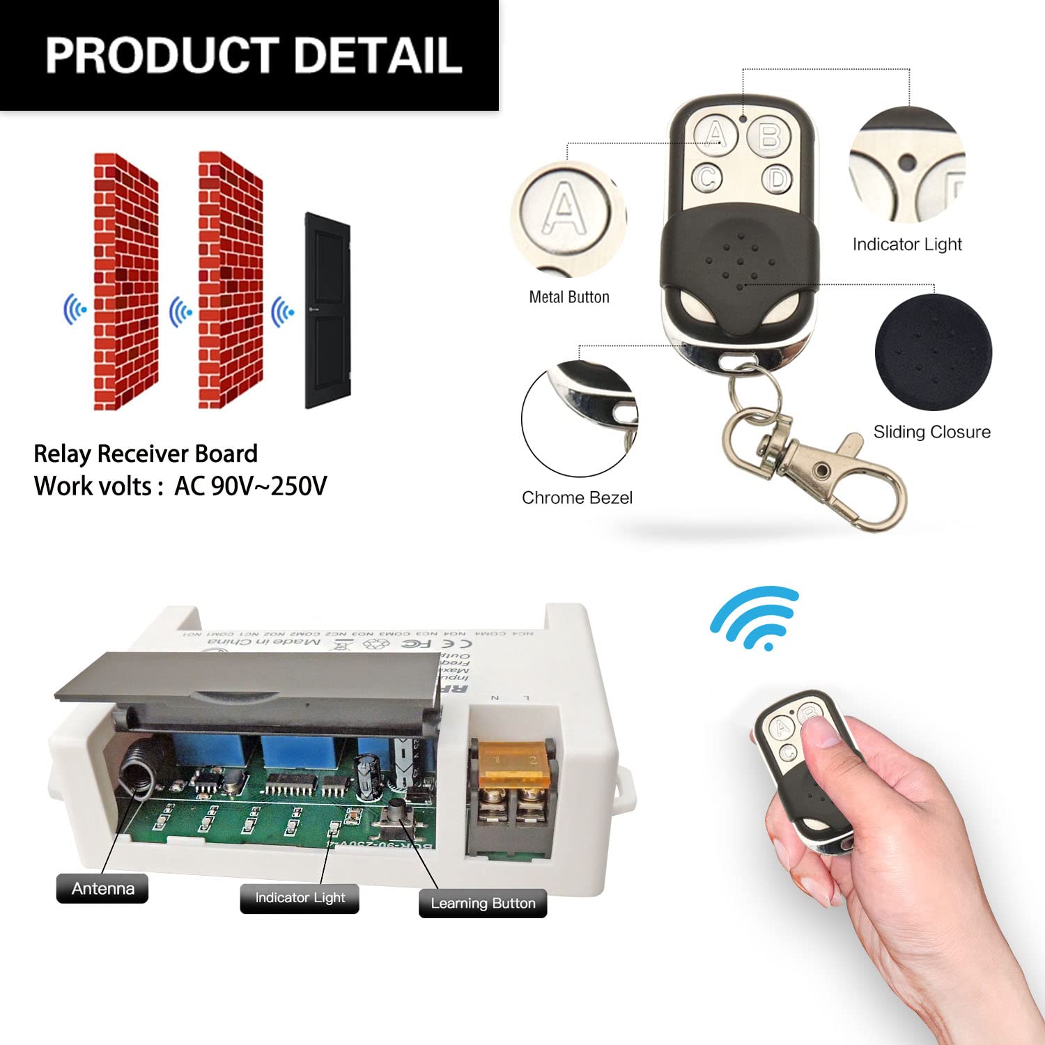
Product Detail

- Receiver unit includes: antenna for signal reception, protective shell, indicator light, learning button for programming
- Remote control features: ‘ON’ and ‘OFF’ silicone buttons, chrome bezel, metal keychain for portability
- NO: Normally open pin
- COM: Common pin
- NC: Normally closed pin
- Output Type: Active output (or passive output / potential-free contacts as applicable)
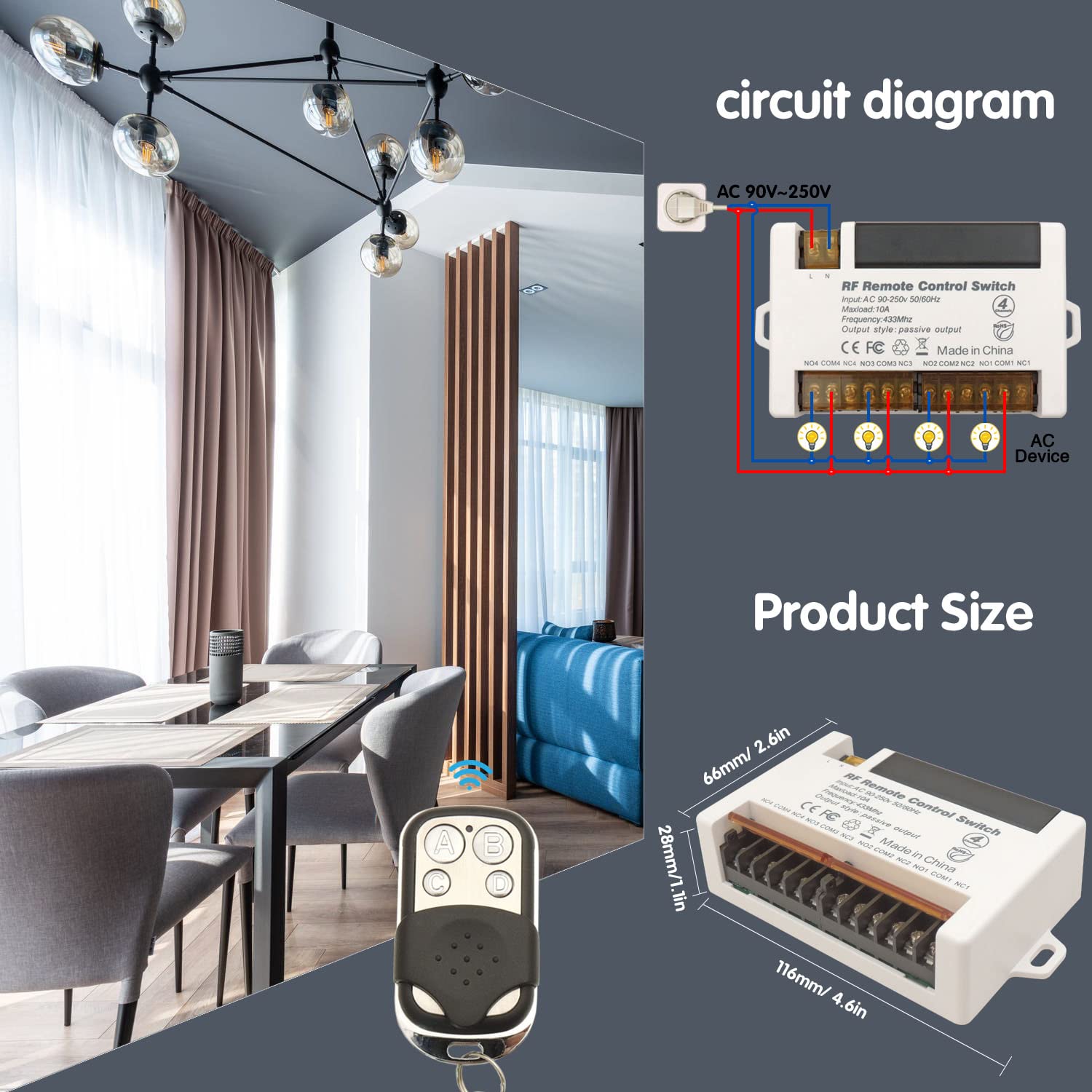
Wiring Diagram


Warning
- Always disconnect power before performing any wiring or maintenance.
- Ensure all connections are secure and properly insulated to prevent short circuits.
- Do not exceed the maximum current rating of 30A for the relay.
- Operate the device within the specified voltage range of AC 85V-250V.
- Keep the device away from water and high humidity environments.
- If you are unsure about electrical wiring, consult a qualified electrician.
- Usually the receiver and transmitter have been paired with each other in factory. If not, please reprogram them.
- Reset before you want to change the operating mode.
- After reset, all the remote controls cannot work anymore.
- Replace the battery in time when the remote transmitter voltage is low to get stronger signal transmission.
- Slightly stretch the antenna on the receiver for better signal reception.
Operating Mode
Momentary Mode (Mode 1)
Press and hold the remote button → relay turns on (output ON)
Release the button → relay turns off
How to program:
- Press the learning button on the receiver 1 time. The indicator light will flash once.
- Press any button on your remote control. The indicator light will flash three times, confirming successful pairing in Momentary Mode.
Toggle Mode (Mode 2)
Press the remote button once → relay turns on (output ON)
Press the same button again → relay turns off
How to program:
- Press the learning button on the receiver 2 times. The indicator light will flash twice.
- Press any button on your remote control. The indicator light will flash three times, confirming successful pairing in Toggle Mode.
Latched Mode (Mode 3)
Press the ON button → relay turns on
Press the OFF button → relay turns off
How to program:
- Press the learning button on the receiver 3 times. The indicator light will flash three times.
- Press the ON button on your remote control.
- Press the OFF button on your remote control. The indicator light will flash three times, confirming successful pairing in Latched Mode.
Delay Mode (Mode 4/5/6/7)
Press the remote button → relay turns on (output ON)
After the set delay time, relay automatically turns off
Delay options:
- Mode 4 (press learning button 4 times): 5-second delay
- Mode 5 (press learning button 5 times): 10-second delay
- Mode 6 (press learning button 6 times): 15-second delay
- Mode 7 (press learning button 7 times): 20-second delay
How to program:
- Press the learning button on the receiver the desired number of times (4, 5, 6, or 7). The indicator light will flash accordingly.
- Press any button on your remote control. The indicator light will flash three times, confirming successful pairing in Delay Mode.
Reset
Press the learning button on the receiver 8 times. The indicator light will flash eight times and then turn off, indicating a successful reset. After reset, the remote control will no longer function until re-paired.

Troubleshooting
If the receiver and transmitter cannot operate normally, try the following steps:
- Remote not responding: Ensure the receiver is powered on and the remote control has a working battery. If the receiver was recently reset, re-pair the remote control following the programming instructions.
- Appliance not turning ON/OFF: Check all wiring connections for tightness and proper insulation. Verify that the power supply to the receiver is active and within the specified voltage range (AC 85V-250V).
- Reduced remote range: Large metal objects, thick walls, or other radio frequency devices can interfere with the signal. Try repositioning the receiver or remote control.
- Indicator light not flashing during programming: Ensure you are pressing the learning button correctly and for the appropriate duration as specified for each mode.
- Battery check: The indicator LED on the remote transmitter does not light up or is dimly lit – replace the battery.
Maintenance
- Keep the receiver and remote control clean and free from dust and debris.
- Avoid exposing the devices to extreme temperatures, direct sunlight, or moisture.
- Replace the remote control battery when its performance degrades.
- Periodically check wiring connections for any signs of wear or damage.
Contact
- WhatsApp: +86 15812381273
- Email: linktrol@icloud.com
If there is any question about the products, please contact us first. We will do our best to solve your problem. Thank you.

2 - SWITNEX Tuya WiFi RF Garage Controller User Manual
SWITNEX Tuya WiFi RF Garage Controller User Manual
| Technical Data | |
|---|---|
| Model Number | SWITNEX Tuya WiFi RF Garage Controller DC AC 12V 24V |
| Origin | Mainland China |
| Certification | CE, CCC, RoHS |
| Control Ways | Tuya APP + 433MHz RF + Voice |
| Wi-Fi Standard | IEEE 802.11 b/g/n (2.4GHz) |
| Working Voltage | DC / AC 5V ~ 48V (12V, 24V supported) |
| Max Current | 3A |
| Code Support | Rolling code (HCS301), Learning code (EV1527), Fixed code (PT2262) |
| Working Modes | Momentary / Toggle (selectable via jumper) |
| Receiver Dimensions | 94 x 60 x 28 mm |
| RF Remote Dimensions | 60 x 30 mm |
| RF Remote Battery | 2 x CR2016 (included) |
| Remote Storage | Up to 32 remotes |
| RF Range | Up to 30 meters (open area) |
| Channels | 2 independent relays |
| Modulation | ASK |
| Smart Home Compatibility | Tuya, Smart Life, Amazon Alexa, Google Home, Alice |
| Material | High-quality plastic |
Product Detail

- Receiver unit – 94x60x28mm, includes 2-channel relay output, dry contact
- 2 x RF remotes (optional button count: 2 or 4 buttons) – 60x30mm, powered by 2x CR2016 batteries (included)
- Jumper cap – for selecting operating mode (M = Momentary, T = Toggle)
- Learning button 1 – for pairing channel 1
- Learning button 2 – for pairing channel 2
- RF indicator – shows RF signal status
- Power indicator – shows power status
- WiFi indicator – shows network connection status
- WiFi module – for Tuya app connectivity
- Input port – AC/DC 5-48V power input
- Output port – connects to garage door/gate control system
- Antenna – for RF signal reception
Wiring Diagram

- Power input: Connect AC or DC 5-48V to input port (polarity not required for AC)
- Output: Connect to garage door opener or gate control system (dry contact relay)
- Compatible with FAAC, DITEC, NICE, BFT, DOORHAN, and other brands
Warning
- Always disconnect power before performing any wiring or maintenance.
- Ensure the input voltage is within DC/AC 5-48V and current does not exceed 3A.
- Installation should be performed by a qualified electrician if unsure.
- Keep the device away from water, moisture, and extreme temperatures.
- The receiver is not waterproof; install in a dry location.
- Usually the receiver and transmitter have been paired in factory. If not, reprogram them.
- Replace remote batteries (2x CR2016) when range decreases or LED dims.
Operating Mode
The receiver supports two operating modes, selected via the jumper cap on the board.
Momentary Mode (Jumper connected to “M”)
Press and hold a button → corresponding relay activates
Release the button → relay deactivates
How to set: Connect the jumper cap to the M position on the board.
Toggle Mode (Jumper connected to “T”)
Press a button once → relay activates
Press the same button again → relay deactivates
How to set: Connect the jumper cap to the T position on the board.
Note: Both channels operate in the same mode. You cannot set one channel to Momentary and the other to Toggle.
Pairing RF Remotes
After selecting the desired mode (M or T), follow these steps to pair the remote controls:
Pair Channel 1 (Button A):
- Press learning button 1 once. The RF indicator will light up.
- Press button A on the remote once. The indicator will flash, confirming successful pairing.
- Button A now controls channel 1.
Pair Channel 2 (Button B):
- Press learning button 2 once. The RF indicator will light up.
- Press button B on the remote once. The indicator will flash, confirming successful pairing.
- Button B now controls channel 2.
Repeat the process for additional remotes (up to 32 remotes total).
Tuya APP & Voice Control
- Download Tuya Smart or Smart Life app from your app store.
- Register or log in to your account.
- Tap ’+’ to add a device.
- Ensure the receiver is powered on and the WiFi indicator is blinking (pairing mode).
- Follow in-app instructions to connect the receiver to your 2.4GHz Wi-Fi network.
- Once connected, you can control the garage door/gate remotely, set schedules, countdown timers, and loop timers.
- Link your Tuya account with Amazon Alexa, Google Home, or Alice for voice control (e.g., “Alexa, open the garage door”).

Reset (Clear Paired Remotes)
To clear all paired RF remotes from the receiver’s memory, press and hold learning button 1 and learning button 2 simultaneously for about 5-8 seconds until the indicators flash rapidly. All stored remotes will be cleared. Re-pair as needed.

Troubleshooting
| Problem | Possible Cause | Solution |
|---|---|---|
| Receiver not responding to remote | Wrong mode jumper setting; Remote not paired; Low battery; Out of range | Check jumper (M/T); Re-pair remote; Replace 2x CR2016 batteries; Move within 30m |
| Cannot connect to Tuya app | Wi-Fi is 5GHz; Wrong password; Receiver not in pairing mode | Use 2.4GHz Wi-Fi; Verify password; Reset WiFi module (press pairing button 5s) |
| Garage door/gate moves wrong direction | Wiring polarity issue | Swap the two output wires to the motor |
| One channel works, other does not | Learning button 2 not pressed; Remote button faulty | Re-pair channel 2 (press learning button 2 then remote button B); Test with another remote |
| Voice control not working | Account not linked; Device name incorrect | Link Tuya account in Alexa/Google Home app; Use correct device name |
Maintenance
- Cleaning: Wipe the receiver and remote with a dry, soft cloth. Do not use liquid cleaners.
- Battery replacement: Replace remote batteries (2x CR2016) when range decreases or LED dims. Ensure correct polarity.
- Firmware updates: Check Tuya app for available firmware updates to ensure optimal performance.
- Storage: Store in a cool, dry place away from direct sunlight and moisture.
Contact
- WhatsApp: +86 15812381273
- Email: linktrol@icloud.com
If there is any question about the products, please contact us first. We will do our best to solve your problem. Thank you.


3 - SITNEX Waterproof Wireless Remote Control Switch (AC 85V-250V, 30A) User Manual
SITNEX Waterproof Wireless Remote Control Switch (AC 85V-250V, 30A) User Manual
| Technical Data | |
|---|---|
| Receiver Working Voltage | AC 85V~250V |
| Quiescent Current | <5MA |
| Max Current | 30A |
| RF frequency | 433MHz |
| Working temperature | -30~+80℃ |
| Receiving Sensitivity | >97dbm |
| Storage remote controls | Up to 20 pieces |
| Support encoding | 1527 Leaning code |
| RF Operating mode | ASK superheterodyne wireless reception |
| Receiving range (open space) | More than 50 meters |
| Waterproof Grade | IP65 |
| Remote operating mode | Momentary / Toggle / Latched |
| Transmitter Battery | 2x CR2016 (included) |
| Relay lifespan | Over 100,000 times |
| Max Load Power | 7200 Watts |
| Dimensions (Receiver) | 0.9 x 0.9 x 0.4 cm (0.35 x 0.35 x 0.15 inches) |
| Material | Aluminum |
| Certifications | CE, FCC |
Product Detail
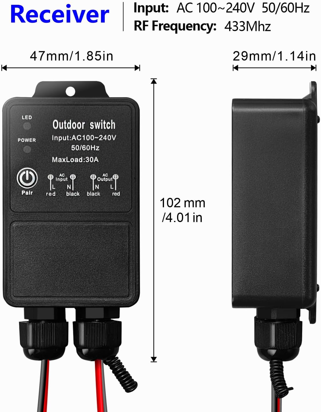
- Receiver unit – IP65 waterproof rating, suitable for indoor and outdoor use (rain and sand resistant), aluminum housing
- 2 x Transmitters – remote controls with ON/OFF buttons, 2x CR2016 batteries included
- 30A high-power relay – can load high-power electrical appliances for long-term stable control
- Learning button on receiver – for programming modes and resetting
- Indicator LED on receiver – provides visual feedback
- Antenna on receiver – extend for better signal reception (improves penetration through walls, floors, doors)
- Input/Output terminals – screw terminals for AC 85V-250V connections (L and N)
Wiring Diagram

- Input: Connect AC 85V-250V Live (L) and Neutral (N) to receiver input terminals
- Output: Connect device (pump, motor, lamp, fan, etc.) to output terminals (L and N)
- Ensure all connections are secure and properly insulated
Warning
- Always disconnect power before performing any wiring or maintenance.
- Ensure all wiring connections are secure and properly insulated.
- Do not exceed the maximum current rating of 30A (7200W).
- The product is IP65 waterproof (resists rain and sand), but do not soak it in water.
- Keep remote controls away from children.
- Usually the receiver and transmitter have been paired in factory. If not, reprogram them.
- Reset before you want to change the operating mode.
- After reset, all remote controls cannot work anymore.
- Replace the battery in time when the remote transmitter voltage is low.
- Slightly stretch the antenna on the receiver for better signal reception.
Operating Mode
The product is pre-set to Latched mode by default. Follow the steps below to change modes.
Momentary Mode
Press and hold a button → relay turns ON
Release the button → relay turns OFF
How to program:
- Press the learning button on the receiver 1 time. Wait 3 seconds.
- Press the ON button on the transmitter. Wait 3 seconds.
- Press the OFF button on the transmitter. Setup complete.
Toggle Mode
Press a button once → relay turns ON
Press the same button again → relay turns OFF
How to program:
- Press the learning button on the receiver 2 times. Wait 3 seconds.
- Press the ON button on the transmitter. Wait 3 seconds.
- Press the OFF button on the transmitter. Setup complete.
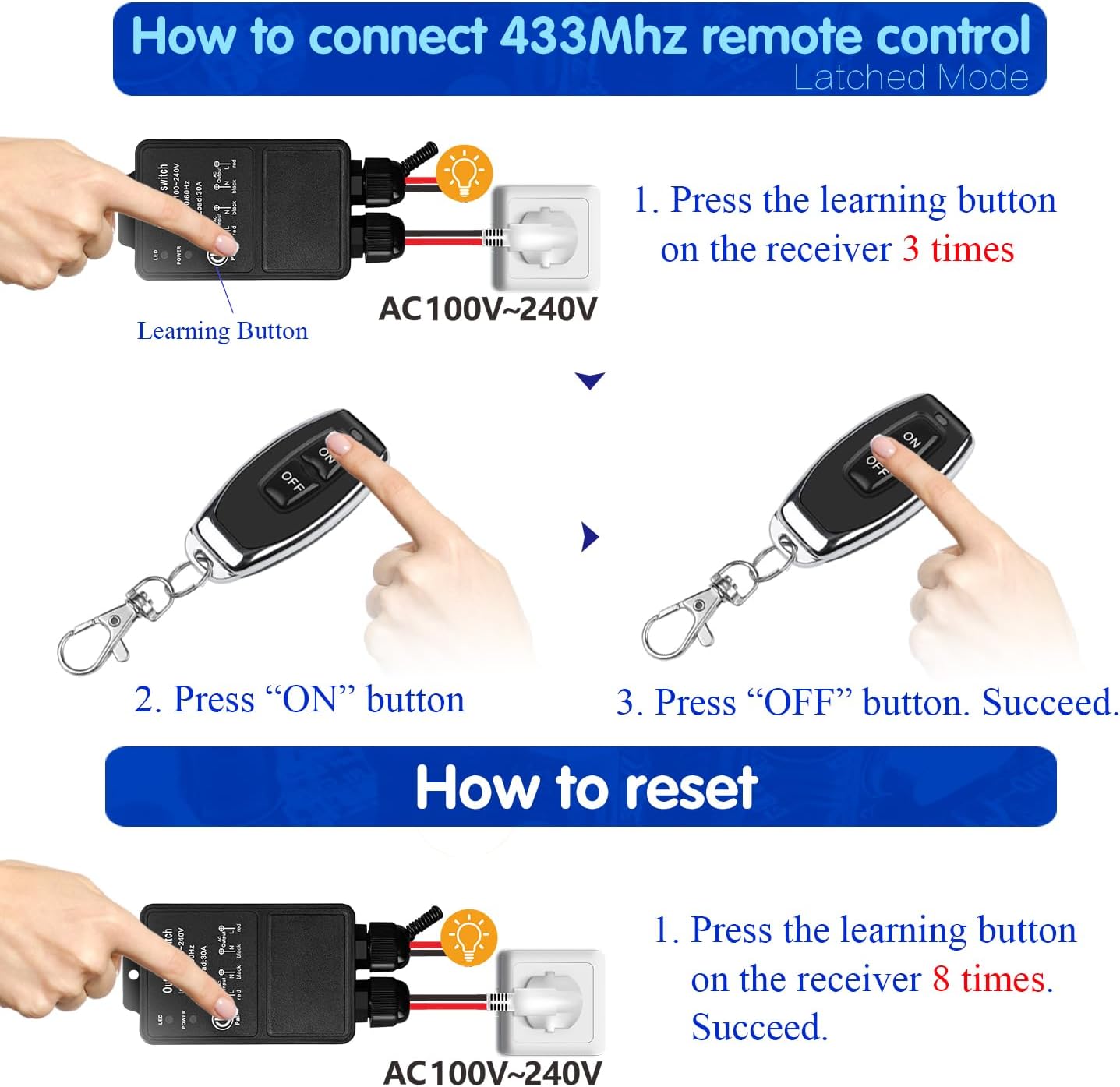
Latched Mode (Default)
Press ON button → relay turns ON
Press OFF button → relay turns OFF
How to program:
- Press the learning button on the receiver 3 times. Wait 3 seconds.
- Press the ON button on the transmitter. Wait 3 seconds.
- Press the OFF button on the transmitter. Setup complete.
Reset
To clear all paired remote controls from the receiver’s memory, press the learning button 8 times consecutively. The reset is successful. After reset, previously paired remote controls will no longer function.
Troubleshooting
If the receiver and transmitter cannot operate normally, try the following steps:
- No response from receiver: Check power supply (AC 85V-250V). Ensure transmitter batteries (2x CR2016) are not depleted. Verify pairing (re-pair if needed). Check for obstructions or excessive distance (up to 50m open space).
- Intermittent operation: Weak transmitter battery (replace). Interference from other RF devices. Extend receiver antenna for better signal.
- Incorrect operating mode: Reprogram the desired mode (see Operating Mode).
- Device not activating under high load: Ensure load does not exceed 30A (7200W). Check relay condition (designed for over 100,000 operations).
Maintenance
- Cleaning: Wipe with a soft, dry cloth. Do not use liquid cleaners.
- Battery replacement: Replace transmitter batteries (2x CR2016) when range decreases or LED dims. Ensure correct polarity.
- Waterproofing: IP65 design resists rain and sand, but avoid submersion. Check seals periodically.
- Storage: Store in a cool, dry place when not in use.
Contact
- WhatsApp: +86 15812381273
- Email: linktrol@icloud.com
If there is any question about the products, please contact us first. We will do our best to solve your problem. Thank you.
4 - SWITNEX Mini Wireless WiFi Switch User Manual
SWITNEX Mini Wireless WiFi Switch User Manual
| Technical Data | |
|---|---|
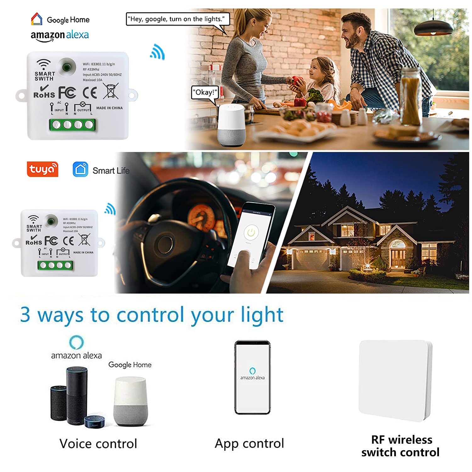
| Control Methods | Tuya APP, Amazon Alexa, Google Home, RF Wireless Wall Switch |
| Maximum Load (General) | 2500W |
| Maximum Load (LED/CFL/Fluorescent) | 300W |
| Wireless Standard | Wi-Fi 2.4 GHz |
| RF frequency | 433MHz |
| Receiver Dimensions | 47 x 42 x 23 mm |
| Restart Status Memory | Configurable (remember last state) |
| Family Sharing | Supported |
Product Detail
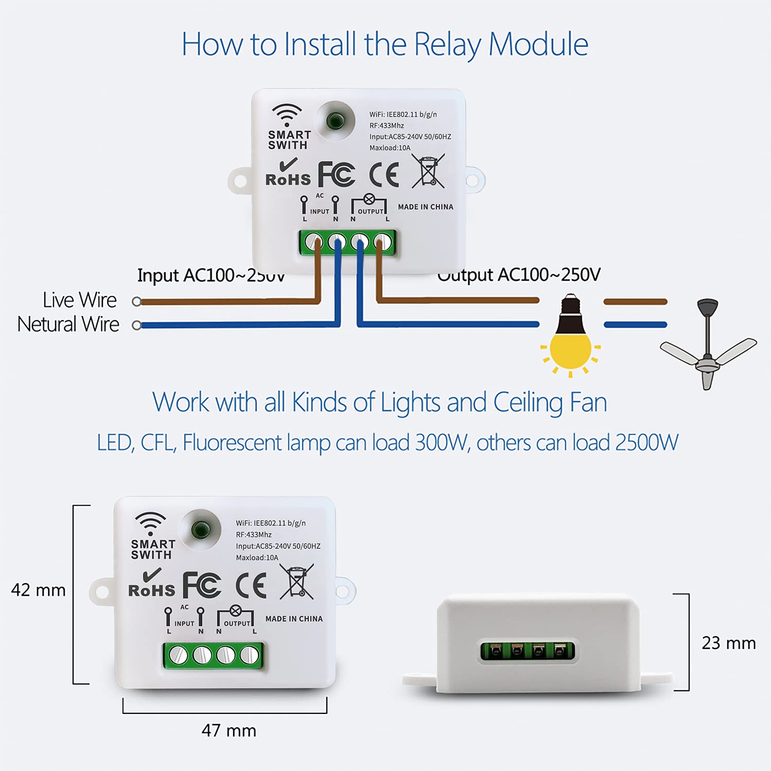
- 3 x Mini Wireless WiFi Relay Receivers – compact design (47x42x23mm), screw terminals for L/N input and output
- 1 x Wireless Wall Switch – multi-gang, RF 433MHz control
- Pairing button on each receiver – for Wi-Fi and RF pairing
- Indicator light on receiver – shows status and pairing mode
Wiring Diagram
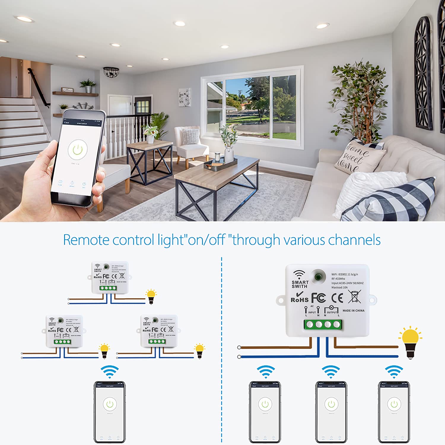
- Power input: Connect Live (L) to ‘L INPUT’, Neutral (N) to ‘N INPUT’
- Appliance output: Connect Live (L) to ‘L OUTPUT’, Neutral (N) to ‘N OUTPUT’
- Mount receiver in electrical box with adequate ventilation
Warning
- Always disconnect power at the main circuit breaker before performing any wiring.
- If unsure about electrical wiring, consult a qualified electrician.
- Do not exceed maximum load (2500W general, 300W for LED/CFL/fluorescent).
- Ensure Wi-Fi network is 2.4 GHz (5 GHz not supported).
- Keep device away from water, moisture, and extreme temperatures.
Operating Mode
RF Wireless Wall Switch Control
The wireless wall switch communicates with the relay module via 433MHz RF.
How to pair:
- Ensure the relay module is powered on.
- Press and hold the pairing button on the relay module for 3-5 seconds until the indicator light blinks rapidly.
- Within 10 seconds, press any button on the wireless wall switch.
- The indicator light will stop blinking and remain solid momentarily, confirming successful pairing.
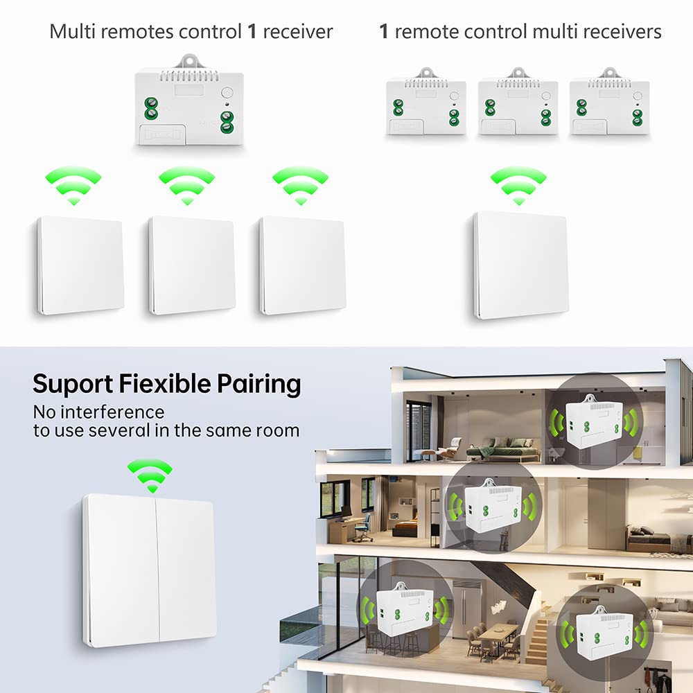
Multi-control options:
- Multiple wall switches can control a single receiver
- One wall switch can control multiple receivers
APP Control (Tuya Smart / Smart Life)
- Download Tuya Smart or Smart Life app from your app store (iOS/Android).
- Register or log in to your account.
- Tap ’+’ or ‘Add Device’.
- Select ‘Electrical’ > ‘Switch (Wi-Fi)’ or ‘Smart Switch’.
- Follow in-app instructions to connect the relay module to your 2.4 GHz Wi-Fi network.
- Once connected, rename the device and control from anywhere.
Voice Control (Amazon Alexa / Google Home)
- Open the Amazon Alexa or Google Home app.
- Navigate to ‘Skills & Games’ (Alexa) or ‘Works with Google’ (Google Home).
- Search for ‘Tuya Smart’ or ‘Smart Life’ and enable the skill/service.
- Link your Tuya/Smart Life account when prompted.
- Discover devices.
- Voice command examples:
- “Alexa, turn on the light”
- “Hey Google, turn off the fan”
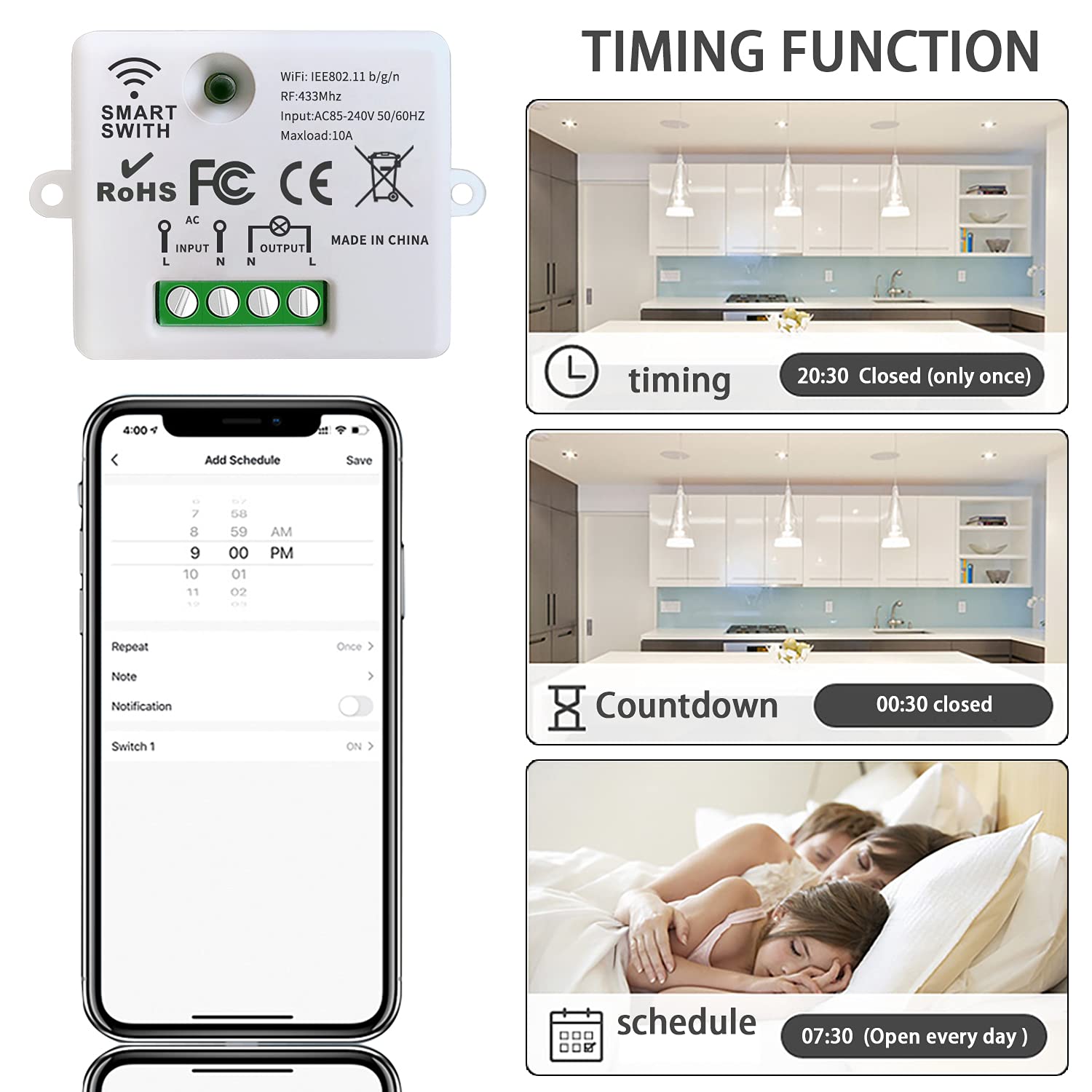
Scheduling and Timers
Set schedules, countdowns, and loop timers for automated operation via the app:
- Schedule: Set specific times for devices to turn on/off
- Countdown: Set a timer after which the device turns off
- Loop timer: Repeat on/off cycles at intervals
Restart Status Memory
Configure the device to remember its last state after a power interruption (configurable in the app).
Family Sharing
Share control of devices with family members through the app.
Troubleshooting
If the receiver and switch cannot operate normally, try the following steps:
- Module not connecting to Wi-Fi: Ensure 2.4 GHz network (not 5 GHz). Check password. Move closer to router during pairing. Reset module and retry.
- Wall switch not responding: Check module is powered. Re-pair switch (press pairing button 3-5 seconds, then press switch button). Ensure within RF range (up to 50 meters open area).
- App control not working: Check internet connection. Ensure Wi-Fi indicator is solid. Restart app.
- Voice control not responding: Verify account linking. Discover devices again. Use correct device names.
Maintenance
- Keep receiver modules dry and free from dust. Use a soft, dry cloth for cleaning.
- Avoid exposing to direct sunlight, high humidity, or corrosive environments.
- Periodically check wiring connections for security.
- Ensure adequate ventilation if installed in enclosed spaces.
Contact
- WhatsApp: +86 15812381273
- Email: linktrol@icloud.com
If there is any question about the products, please contact us first. We will do our best to solve your problem. Thank you.
5 - SWITNEX Kinetic Wireless Light Switch and 10A Relay Receiver Kit User Manual
SWITNEX Kinetic Wireless Light Switch and 10A Relay Receiver Kit User Manual
| Technical Data | |
|---|---|
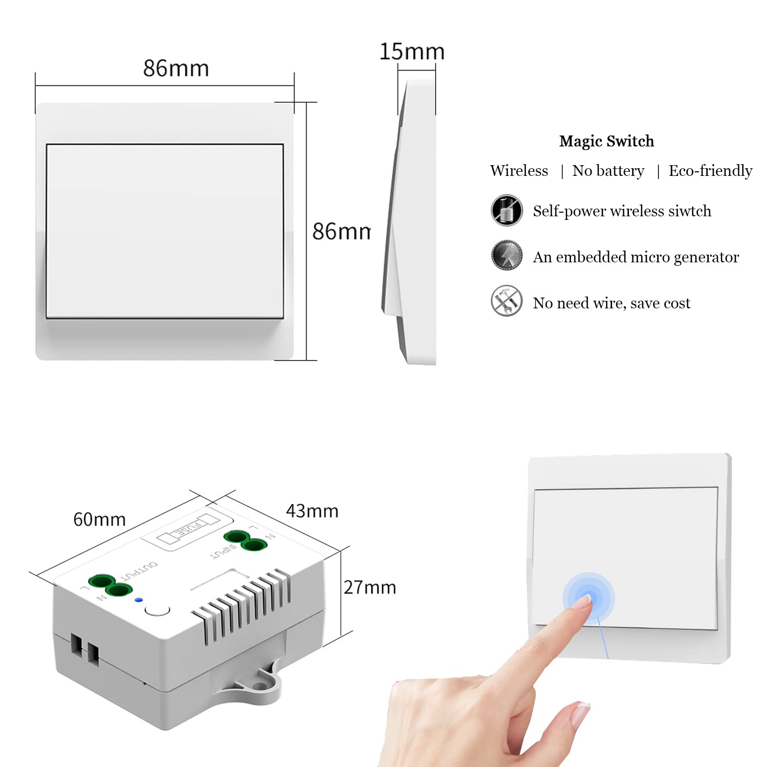
| Switch Type | Kinetic Wireless Self-Generating Switch |
| Receiver Type | RF 433 MHz Relay Receiver |
| Operating Voltage (Receiver) | AC 110V-240V |
| Max Load (Receiver) | 10A / 1500W |
| Fuse | 10A (Replaceable) |
| Wireless Frequency | 433 MHz |
| Indoor Control Distance | Up to 50 meters |
| Outdoor Control Distance | Up to 100 meters (open space) |
| Switch Lifespan | > 200,000 clicks |
| Relay Lifespan | > 400,000 operations |
| Waterproof Rating (Switch) | IPX4 |
| Material | Plastic |
| Switch Dimensions (L x W x H) | 86mm x 86mm x 11mm |
| Receiver Dimensions (L x W x H) | 60mm x 43mm x 27mm |
| Operating Mode | ON-OFF |
| Connector Type | Screw Terminals |
Product Detail
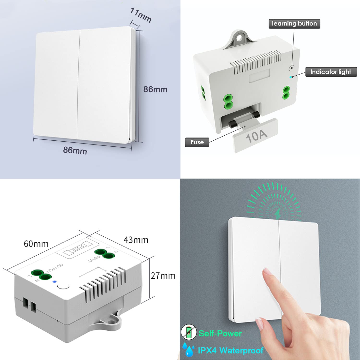
- 1 x Kinetic Wireless Switch – self-generating, no battery required, IPX4 waterproof, 86x86x11mm
- 1 x Relay Receiver – 10A relay, 433MHz RF, 60x43x27mm, includes learning button, indicator light, replaceable 10A fuse
- Mounting accessories – screws, double-sided tape
- Receiver terminals: L INPUT / N INPUT (power supply), L OUTPUT / N OUTPUT (to appliance)
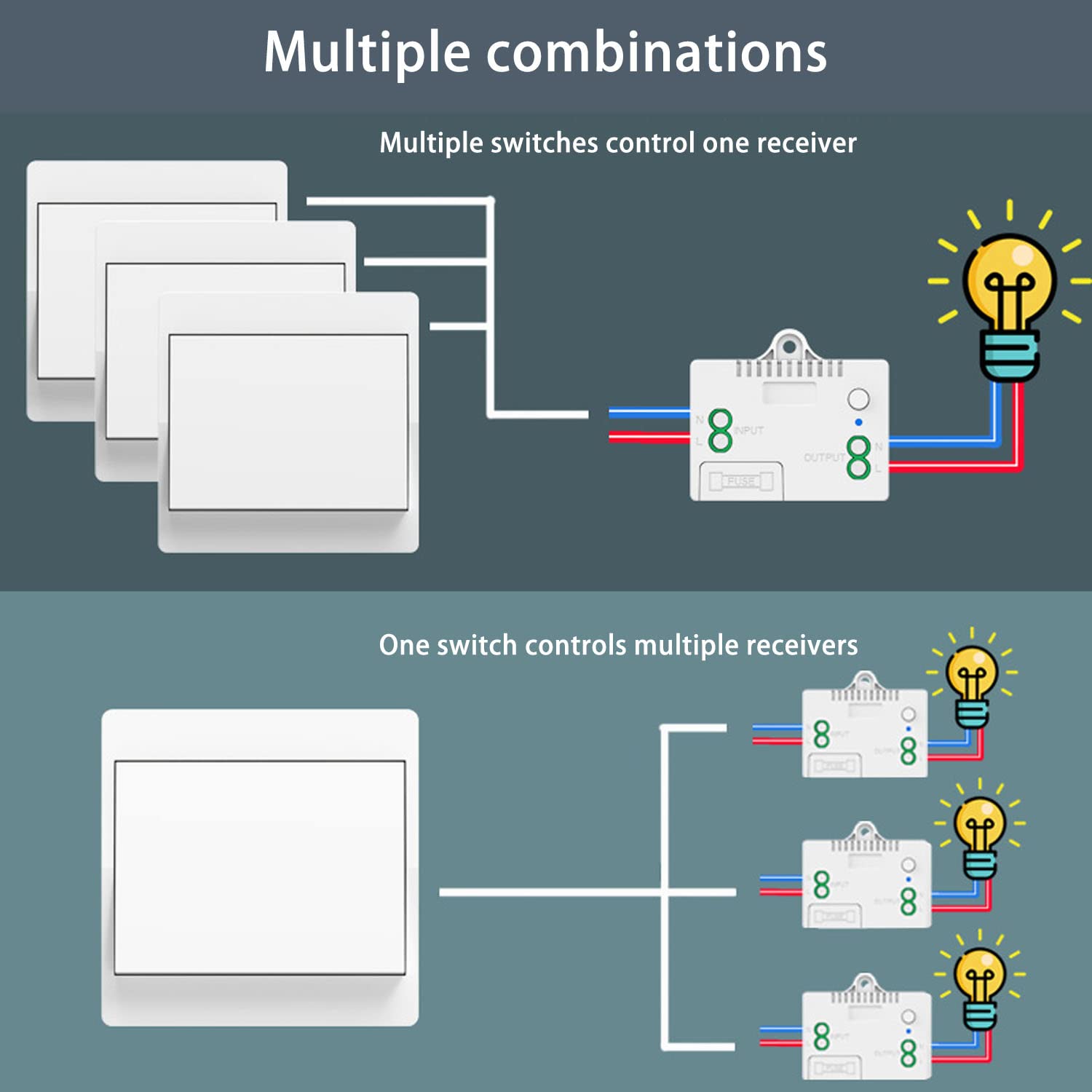
Wiring Diagram
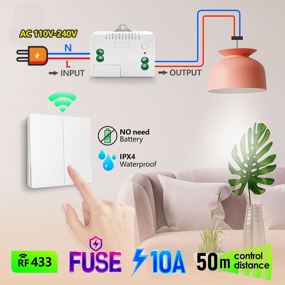
- Power input: Connect AC 110V-240V Live (L) to ‘L INPUT’, Neutral (N) to ‘N INPUT’
- Appliance output: Connect appliance Live (L) to ‘L OUTPUT’, Neutral (N) to ‘N OUTPUT’
- Maximum load: 1500W / 10A
Warning
- Always disconnect power at the circuit breaker before installing or servicing the receiver.
- Installation should be performed by a qualified electrician or a person with sufficient electrical knowledge.
- Ensure the receiver’s load does not exceed 1500W (10A at 110V-240V AC).
- The wireless switch is IPX4 waterproof, suitable for damp environments, but avoid submerging it in water.
- Do not attempt to repair or modify the device. Contact customer support for assistance.
- Usually the receiver and transmitter have been paired in factory. If not, reprogram them.
- Reset before you want to change the operating mode or add new switches.
- After reset, all previously paired switches will no longer work.
Operating Mode
Toggle Mode (Default)
Press the kinetic switch once → connected device turns ON
Press the switch again → connected device turns OFF
How to program (pairing):
- Press and hold the learning button on the receiver for approximately 3-5 seconds. The blue indicator light will illuminate. Release the button.
- Within a few seconds, press the button on the kinetic wireless switch once.
- The indicator light will flash, confirming successful pairing.
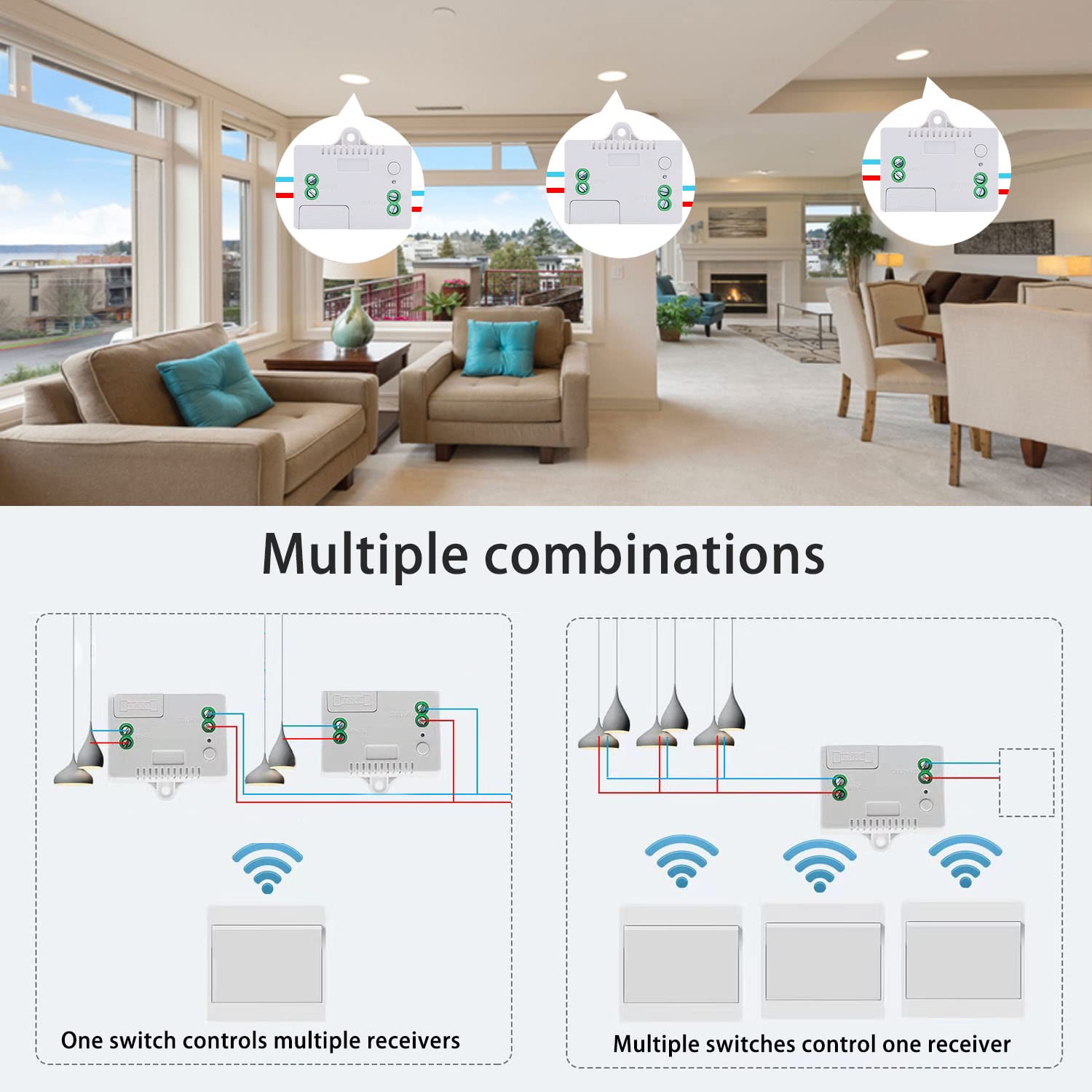
Multi-Control Scenarios
- Multiple switches control one receiver: Pair up to 5 wireless switches with a single receiver (e.g., top and bottom of stairs).
- One switch controls multiple receivers: A single wireless switch can be paired with multiple receivers to control several appliances simultaneously.
Control Distance
- Indoor: Up to 50 meters (signal passes through walls, floors, doors)
- Outdoor (open space): Up to 100 meters
Reset (Clear Paired Signals)
To clear all paired signals from the receiver (e.g., when replacing a switch or reconfiguring), press and hold the learning button for approximately 8-10 seconds. The indicator light will flash multiple times, confirming that all stored signals have been cleared.

Troubleshooting
| Problem | Possible Cause | Solution |
|---|---|---|
| Appliance does not turn ON/OFF | No power to receiver; Switch not paired; Receiver fuse blown; Appliance malfunction | Check power supply; Perform pairing steps; Check/replace 10A fuse; Test appliance directly |
| Reduced control distance or intermittent operation | RF interference; Obstructions (thick walls, metal); Exceeds max range | Relocate receiver/switch; Ensure no metallic obstacles; Operate within 50m indoor |
| Switch feels stiff or unresponsive | Mechanical issue; Debris | Clean switch; Contact support if persists |
Maintenance
- Cleaning: Wipe the switch and receiver with a dry, soft cloth. Do not use abrasive cleaners or solvents.
- Fuse replacement: If receiver stops functioning due to overload, disconnect power, open fuse compartment, replace with same rating (10A).
- Self-powered switch: No battery needed; designed for over 200,000 clicks.
- Relay lifespan: Designed for over 400,000 operations.
Contact
- WhatsApp: +86 15812381273
- Email: linktrol@icloud.com
If there is any question about the products, please contact us first. We will do our best to solve your problem. Thank you.
6 - SWITNEX 4 Channels Wireless Relay Remote Control Switch User Manual
SWITNEX 4 Channels Wireless Relay Remote Control Switch User Manual
| Technical Data | |
|---|---|
| Operation Mode | Toggle, Momentary, Latched |
| Current Rating | 10 Amps |
| Operating Voltage | DC 6V~30V (compatible with 5V, 12V, 24V, 30V) |
| Contact Type | Normally Open, Common, Normally Closed |
| Connector Type | Wireless (433MHz RF) |
| Terminal | Screw |
| Circuit Type | 4-way |
| Actuator Type | Push Button (on remote) |
| Contact Material | Copper |
| Package Dimensions | 5.16 x 3.23 x 2.2 inches |
| Weight | 7.05 ounces |
| Batteries | 2 x 12V batteries (included for transmitters) |
| RF frequency | 433MHz |
| Receiving sensitivity | >-105dBm |
| Receiving range (open space) | Up to 50 meters |
| Storage remote controls | Up to 20 pieces |
| Relay lifespan | Over 100,000 operations |
Product Detail
- Receiver module – 4 independent relays, large screw terminals, learning button, indicator LED
- 2 x Keyfob transmitters – 12V batteries included
- NO: Normally open pin (each relay)
- COM: Common pin (each relay)
- NC: Normally closed pin (each relay)
- Power terminals: VIN (DC 5V-30V positive), GND (negative)
Wiring Diagram

- Power input: Connect DC 6V-30V to VIN (+) and GND (-)
- Relay output (dry contacts): Four independent relays, each with NO/COM/NC
- Compatible cable types: Single-Strand Hard Wire (BV), Stranded Hard Wire (RV), Stranded Flexible Wire (BVR)
Warning
- Always disconnect power before performing any wiring or maintenance.
- Do not exceed the maximum current rating of 10A per relay.
- Ensure input voltage is within DC 6V-30V.
- Keep the device away from moisture, water, and extreme temperatures.
- If unsure about wiring, consult a qualified electrician.
- Usually the receiver and transmitter have been paired in factory. If not, reprogram them.
- Reset before you want to change the operating mode.
- After reset, all remote controls cannot work anymore.
- Replace the battery in time when the remote transmitter voltage is low.
Operating Mode
The receiver supports three operating modes. Follow the programming steps below to set the desired mode.
Momentary Mode
Press and hold a button → relay activates (device ON)
Release the button → relay deactivates (device OFF)
How to program:
- Press the learning button on the receiver 1 time. Wait approximately 3 seconds.
- Press button A on the remote control.
- Press button B on the remote control. Pairing successful.
Toggle Mode
Press a button once → relay activates (device ON)
Press the same button again → relay deactivates (device OFF)
How to program:
- Press the learning button on the receiver 2 times. Wait approximately 3 seconds.
- Press button A on the remote control.
- Press button B on the remote control. Pairing successful.
Latched Mode
Press ON button (e.g., A) → relay activates (device ON)
Press OFF button (e.g., B) → relay deactivates (device OFF)
How to program:
- Press the learning button on the receiver 3 times. Wait approximately 3 seconds.
- Press button A on the remote control.
- Press button B on the remote control. Pairing successful.
Note: Latched mode typically requires a remote with at least two buttons per relay pair. For 4-channel receiver, buttons A/B control Relay 1, and C/D control Relay 2, etc.
Reset
To clear all paired remote controls from the receiver’s memory, press the learning button 8 times consecutively. All previously paired remotes will be cleared. After reset, re-pair remotes as needed.

Troubleshooting
If the receiver and transmitter cannot operate normally, try the following steps:
- Device not responding to remote: Check transmitter batteries (replace if needed). Re-pair remote. Ensure no obstacles (metal objects, thick walls). Verify receiver power (indicator light on).
- Relay not activating/deactivating correctly: Check wiring to NO/COM/NC terminals. Confirm correct operating mode (reprogram if needed). Ensure load does not exceed 10A.
- Remote buttons not lighting up: Replace 12V battery.
- Persistent issues: Reset receiver (press learning button 8 times) and re-pair.
Maintenance
- Keep the receiver and transmitters dry and away from moisture.
- Clean with a soft, dry cloth. Do not use harsh chemicals or abrasive cleaners.
- Replace transmitter batteries when range decreases.
- Avoid extreme temperatures.
- Periodically check wiring connections for security and corrosion.
Contact
- WhatsApp: +86 15812381273
- Email: linktrol@icloud.com
If there is any question about the products, please contact us first. We will do our best to solve your problem. Thank you.


7 - SWITNEX 4-Channel Wireless Relay Remote Control Switch User Manual
SWITNEX 4-Channel Wireless Relay Remote Control Switch User Manual
| Technical Data | |
|---|---|
| Operating Voltage | AC 85V~240V (50/60Hz) |
| Current Rating | 10 Amps (Max Load) |
| Frequency | 433MHz RF |
| Output Style | Passive Output (Dry Contacts) |
| Contact Type | Normally Open (NO), Common (COM), Normally Closed (NC) |
| Remote Control Batteries | 2 x 12V batteries (included) |
| Receiving range (open space) | Up to 50 meters |
| Relay lifespan | Over 100,000 operations |
| Dimensions | 7.36 x 3.78 x 1.54 inches |
| Weight | 7.76 ounces |
| Material | Copper (Contact Material) |
| Country of Origin | China |
| Operating modes | Momentary, Toggle, Latched |
| Number of relays | 4 independent relays |
Product Detail
- Receiver module – 4 independent 10A relays, large screw terminals, learning button, indicator light, transparent flip cover for circuit adjustment
- 2 x Keyfob transmitters – 2 x 12V batteries included
- Each relay has three terminals: NO (Normally Open), COM (Common), NC (Normally Closed)
- Power input terminals: L (Live), N (Neutral) for AC 85V-240V
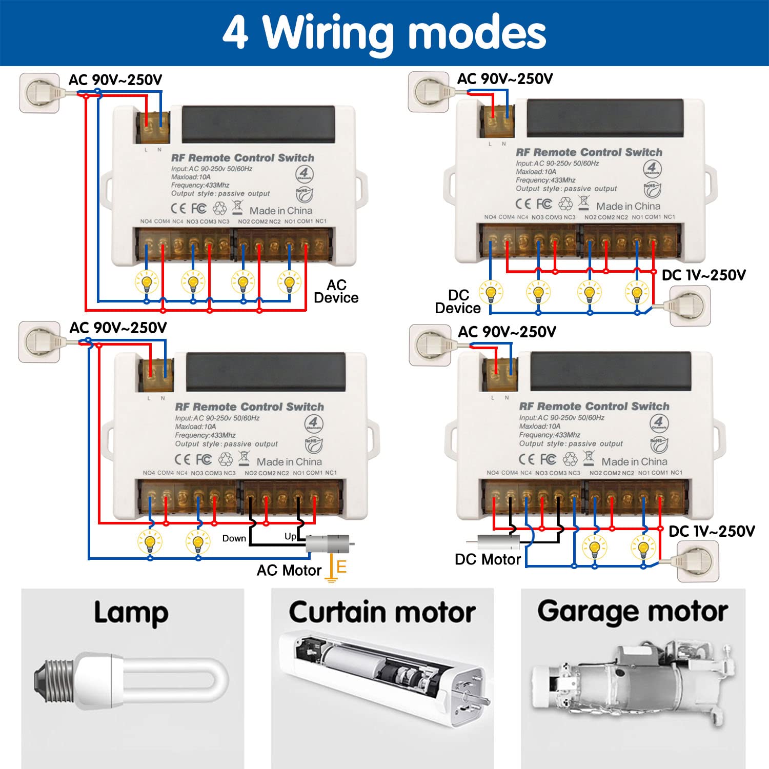
Wiring Diagram
- Power input: Connect AC 85V-240V to L and N terminals
- Relay output (dry contacts): Four independent relays (NO/COM/NC)
- Compatible with various cable types; large screw terminals for easy installation
Warning
- Always disconnect power before performing any wiring or maintenance.
- Do not exceed the maximum current rating of 10A per relay.
- Ensure input voltage is within AC 85V-240V.
- Keep the device away from water, moisture, and extreme temperatures.
- If unsure about wiring, consult a qualified electrician.
- Usually the receiver and transmitter have been paired in factory. If not, reprogram them.
- Reset before you want to change the operating mode.
- After reset, all remote controls cannot work anymore.
- Replace the battery in time when the remote transmitter voltage is low.
Operating Mode
The product is typically pre-programmed in Toggle Mode. Follow the steps below to change modes.
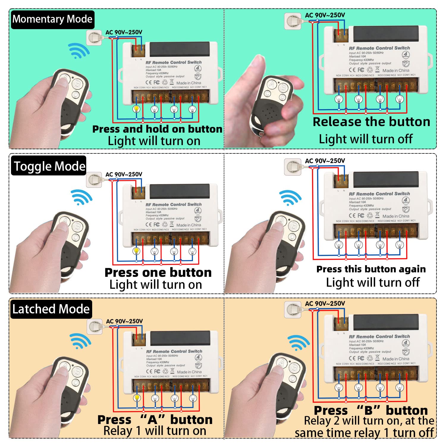
Momentary Mode (Mode 1)
Press and hold a button → relay activates (device ON)
Release the button → relay deactivates (device OFF)
How to program:
- Press the learning button on the receiver 1 time.
- Press button A on the remote control.
- Press button B on the remote control. Pairing successful.
Toggle Mode (Mode 2)
Press a button once → relay activates (device ON)
Press the same button again → relay deactivates (device OFF)
How to program:
- Press the learning button on the receiver 2 times.
- Press button A on the remote control.
- Press button B on the remote control. Pairing successful.
Latched Mode (Mode 3)
Press button A → Relay 1 turns ON, Relay 2 turns OFF
Press button B → Relay 2 turns ON, Relay 1 turns OFF
How to program:
- Press the learning button on the receiver 3 times.
- Press button A on the remote control.
- Press button B on the remote control. Pairing successful.
Note: Latched mode provides alternating control between two relays. It requires a remote with at least 2 buttons for independent control of two relays.
Reset
To clear all programmed remote controls from the receiver’s memory, press the learning button 8 times. The indicator light will flash, confirming the reset. After reset, previously paired remotes will no longer work; re-program as needed.
Troubleshooting
If the receiver and transmitter cannot operate normally, try the following steps:
- No response from remote: Check remote batteries (2 x 12V). Ensure receiver is powered (AC 85V-240V). Verify remote is properly paired. Ensure within 50m range (walls may reduce signal).
- Incorrect operating mode: Re-program the desired mode following the instructions.
- Relay not activating/deactivating: Check wiring connections. Ensure load does not exceed 10A.
Maintenance
- Keep the device clean and free from dust. Use a soft, dry cloth.
- Avoid exposing to extreme temperatures, humidity, or direct sunlight.
- Periodically check wiring connections for security and corrosion.
- Do not open the main receiver unit beyond the learning button access panel.
Contact
- WhatsApp: +86 15812381273
- Email: linktrol@icloud.com
If there is any question about the products, please contact us first. We will do our best to solve your problem. Thank you.


8 - SWITNEX Waterproof Wireless Remote Control DC 8V-80V 30A Radio Control Switch User Manual
SWITNEX Waterproof Wireless Remote Control DC 8V-80V 30A Radio Control Switch User Manual
| Technical Data | |
|---|---|
| Receiver Working Voltage | DC 8V~80V |
| Quiescent Current | <5MA |
| Max Current | 30A |
| RF frequency | 433MHz |
| Working temperature | -30~+80℃ |
| Receiving Sensitivity | >97dbm |
| Storage remote controls | Up to 20 pieces |
| Support encoding | 1527 Leaning code |
| RF Operating mode | ASK superheterodyne wireless reception |
| Receiving range | Open space is more than 50 meters |
| Waterproof Grade | IP65 |
| Remote operating mode | Momentary / Toggle / Latched |
| Transmitter Battery | 2x CR2016 (included) |
Product Detail
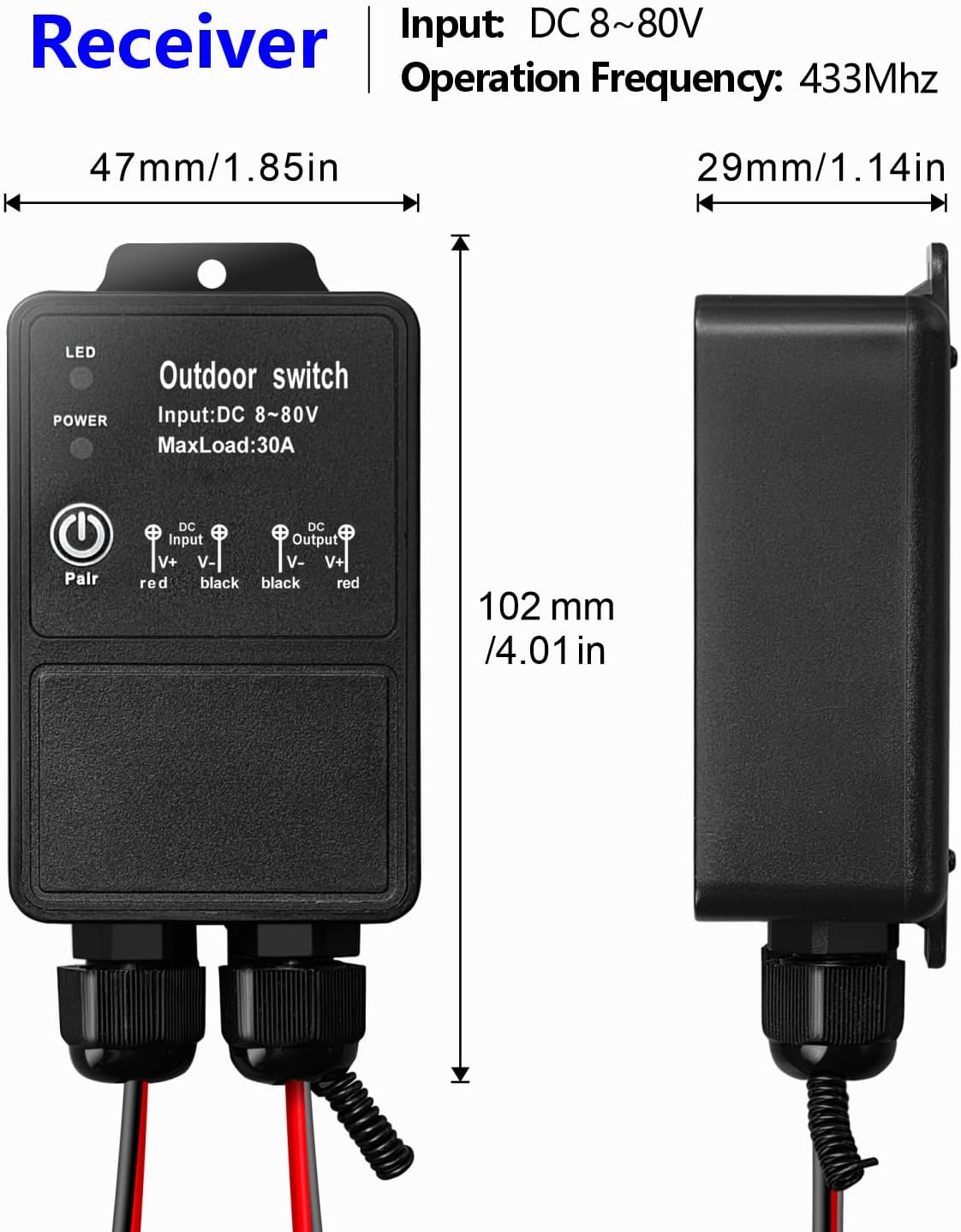
- Receiver unit – IP65 waterproof rating, suitable for outdoor/wet locations
- 2 x Transmitters – remote controls with ON/OFF buttons, 2x CR2016 batteries included
- Learning button on receiver – for programming modes and resetting
- Indicator LED on receiver – provides visual feedback
- Antenna on receiver – extend for better signal reception
- Input/Output terminals – clearly marked for DC 8V-80V connections (V- V+ input, V+ V- output)
Wiring Diagram


- Input: Connect DC 8V-80V power supply to V- (negative) and V+ (positive) input terminals
- Output: Connect device to V+ and V- output terminals
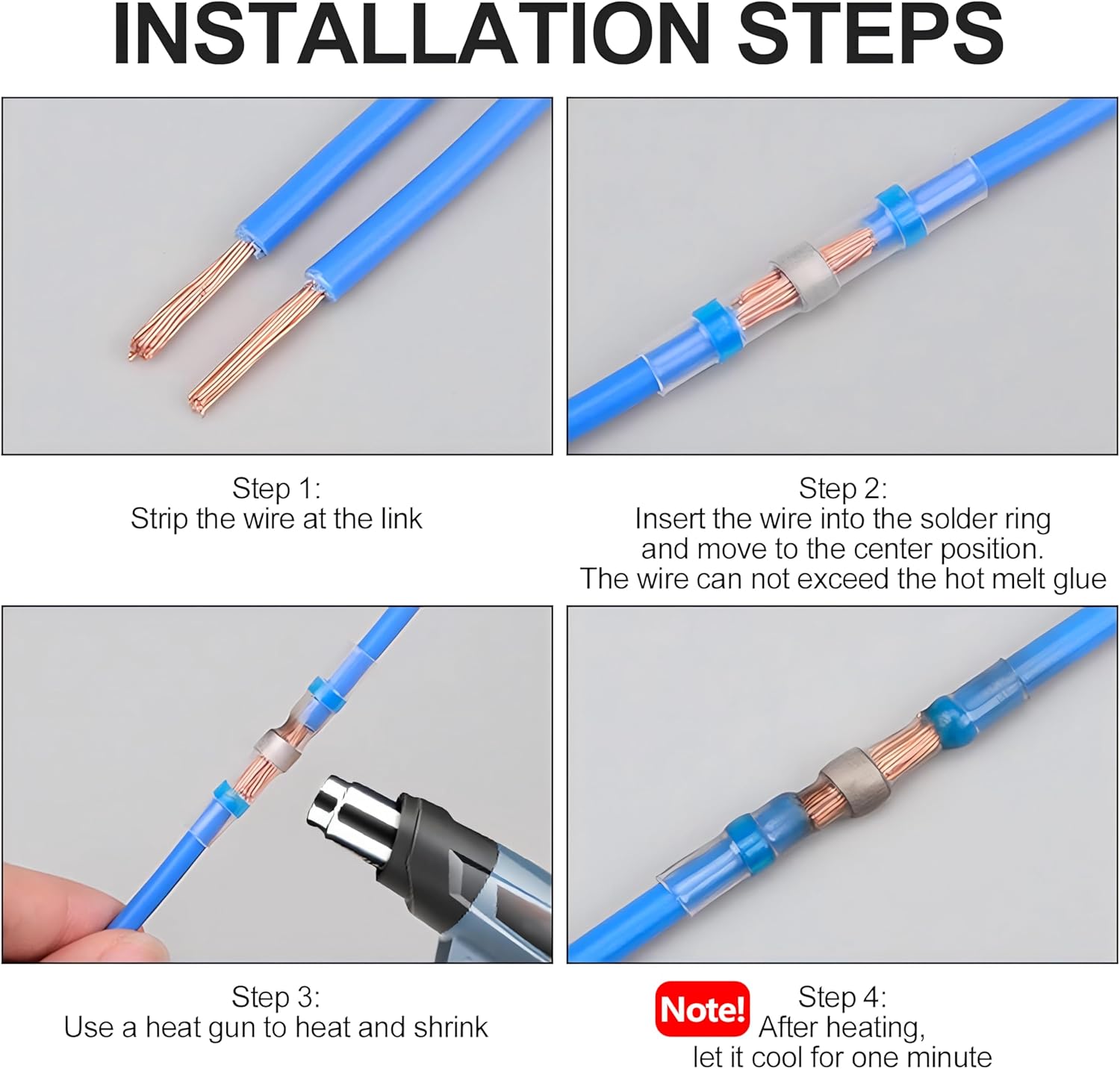
- Use heat shrink solder connectors for secure waterproof connections (strip 5-7mm, insert, heat with heat gun, cool 1 minute)
Warning
- Always disconnect power before performing any wiring or maintenance.
- Ensure all wiring connections are secure and properly insulated.
- Do not exceed the maximum current rating of 30A.
- The product is IP65 waterproof, but avoid prolonged submersion in water.
- Keep remote controls away from children.
- Usually the receiver and transmitter have been paired in factory. If not, reprogram them.
- Reset before you want to change the operating mode.
- After reset, all remote controls cannot work anymore.
- Replace the battery in time when the remote transmitter voltage is low.
- Slightly stretch the antenna on the receiver for better signal reception.
Operating Mode
The product is pre-set to Latched mode by default. Follow the steps below to change modes.
Momentary Mode
Press and hold a button → relay turns ON
Release the button → relay turns OFF
How to program:
- Press the learning button on the receiver 1 time. Wait 3 seconds.
- Press the ON button on the transmitter. Wait 3 seconds.
- Press the OFF button on the transmitter. Setup complete.
Toggle Mode
Press a button once → relay turns ON
Press the same button again → relay turns OFF
How to program:
- Press the learning button on the receiver 2 times. Wait 3 seconds.
- Press the ON button on the transmitter. Wait 3 seconds.
- Press the OFF button on the transmitter. Setup complete.
Latched Mode (Default)
Press ON button → relay turns ON
Press OFF button → relay turns OFF
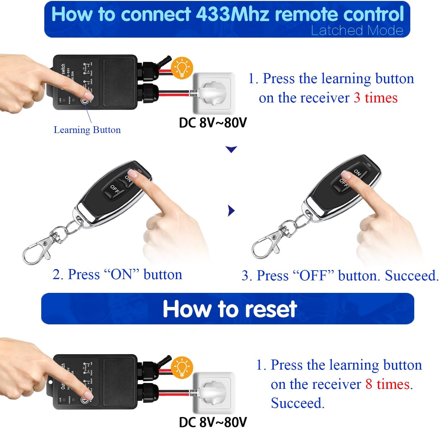
How to program:
- Press the learning button on the receiver 3 times. Wait 3 seconds.
- Press the ON button on the transmitter. Wait 3 seconds.
- Press the OFF button on the transmitter. Setup complete.
Reset
To clear all paired remote controls from the receiver’s memory, press the learning button 8 times consecutively. The reset is successful. After reset, previously paired remote controls will no longer function.
Troubleshooting
If the receiver and transmitter cannot operate normally, try the following steps:
- No response from receiver: Check power supply (DC 8V-80V). Ensure transmitter batteries are not depleted. Verify pairing (re-pair if needed). Check for obstructions or excessive distance.
- Intermittent operation: Weak transmitter battery (replace). Interference from other RF devices. Extend receiver antenna.
- Incorrect operating mode: Reprogram the desired mode (see Operating Mode).
Maintenance
- Cleaning: Wipe with a soft, dry cloth. Do not use liquid cleaners.
- Battery replacement: Replace transmitter batteries (2x CR2016) when range decreases or LED dims. Ensure correct polarity.
- Waterproofing: Check seals periodically. Keep connector points dry and secure.
- Storage: Store in a cool, dry place when not in use.
Contact
- WhatsApp: +86 15812381273
- Email: linktrol@icloud.com
If there is any question about the products, please contact us first. We will do our best to solve your problem. Thank you.
9 - SWITNEX Smart WiFi Relay Module 1CHx4-TEW User Manual
SWITNEX Smart WiFi Relay Module 1CHx4-TEW User Manual
| Technical Data | |
|---|---|
| Model Number | EW748 / 1CHx4-TEW |
| Dimensions (L x W x H) | 55 x 29 x 17 mm (2.2 x 1.1 x 0.7 inches) |
| Input Voltage | DC 5V (via USB) or DC 7V-48V |
| Relay Contact Rating | 10A (AC 250V, DC 30V) |
| Power Consumption | 480 Watts (Max) |
| Wireless Standard | Wi-Fi 2.4 GHz |
| Control Methods | eWelink APP, Bluetooth Remote, Voice Control (Alexa/Google Home) |
| Operating Modes | Inching (Momentary), Self-Locking (Toggle) |
| Material | Plastic |
| Certification | CE |
| Bluetooth Remote | RM2.4G (included), with 4 channel buttons + ALL ON/ALL OFF |
Product Detail

- Smart WiFi Relay Module – compact design (55x29x17 mm)
- Bluetooth RM2.4G remote control – 4 numbered buttons, ALL ON, ALL OFF
- Relay output terminals: NO (Normally Open), COM (Common), NC (Normally Closed) – dry contacts
- Power input options: Micro USB (DC 5V/0.5A) or terminal block (DC 7V-48V)
- Pairing button – also called “Open key” for Wi-Fi pairing
- Relay indicator light – shows relay state
- WiFi network indicator light – shows connection status
Wiring Diagram


- Power input (DC 7V-48V): Connect positive (+) to VIN, negative (-) to GND
- Power input (USB): Connect micro USB cable (5V/0.5A)
- Relay output (dry contact): Connect device control circuit to NO/COM/NC
- Example: For DC device with DC 7V-48V, connect power source to VIN/GND, device to COM/NO
- Example: For AC/DC device (1V-250V), connect external power through COM/NO
Warning
- Always disconnect power before performing any wiring or maintenance.
- Do not exceed the maximum relay rating of 10A at 250V AC or 30V DC.
- Ensure the input voltage is within DC 5V (USB) or DC 7V-48V (terminal).
- Install in a dry, well-ventilated area away from moisture and extreme temperatures.
- Use a qualified electrician if unsure about wiring.
- The module supports 2.4 GHz Wi-Fi only (does not work with 5 GHz networks).
Operating Mode
The module supports two primary operating modes, configurable in the eWelink app.
Inching Mode (Momentary)
When triggered, the relay activates for a set duration (0.5 to 3600 seconds) and then automatically deactivates. Suitable for garage door openers or pulse-triggered devices.
How to configure: In eWelink app, select Inching mode and set desired duration.
Self-Locking Mode (Toggle)
Acts like a standard on/off switch – one trigger turns the relay ON, another trigger turns it OFF. Suitable for lights, fans, and continuous control.
How to configure: In eWelink app, select Self-Locking mode.
APP Control (eWelink)
- Download eWelink app (Android/iOS) from app store or scan QR code.
- Create an account and log in.
- Power on the module.
- Tap ’+’ to add device.
- Press and hold the pairing button on the module until the WiFi indicator blinks rapidly.
- Follow in-app prompts to connect to your 2.4 GHz Wi-Fi network.
- Once paired, you can:
- Turn devices on/off
- Set schedules and timers
- Configure operating modes
- Share control with family members

Bluetooth Remote Control
The included RM2.4G Bluetooth remote allows local operation:
- Buttons 1-4 – control corresponding relay channels (or functions)
- ALL ON – turns all connected devices on
- ALL OFF – turns all connected devices off
The remote is typically pre-paired. If re-pairing is needed, follow the eWelink app instructions.
Voice Control (Alexa / Google Home)
- Link your eWelink account to Amazon Alexa or Google Home through their respective apps.
- Discover devices.
- Use voice commands such as:
- “Alexa, turn on the light”
- “Hey Google, turn off the fan”


Troubleshooting
| Problem | Possible Cause | Solution |
|---|---|---|
| Module not powering on | Incorrect power supply; Loose wiring | Verify DC 5V USB or DC 7V-48V connection; Check cables |
| Unable to connect to Wi-Fi | 5 GHz network; Wrong password; Out of range | Use 2.4 GHz Wi-Fi; Check password; Move closer to router; Reset and re-pair |
| App control not responding | Internet down; Module disconnected | Check smartphone internet; Ensure WiFi indicator is solid; Restart app |
| Voice control not working | Account not linked; Wrong device name | Link eWelink account in Alexa/Google Home; Verify device name in app |
| Bluetooth remote not working | Battery low; Out of range; Not paired | Replace battery; Move closer; Re-pair via eWelink app |
Maintenance
- Cleaning: Wipe with a dry, soft cloth. Do not use liquid cleaners.
- Ventilation: Ensure adequate airflow around the module.
- Avoid moisture: Keep dry and away from humidity.
- Secure connections: Periodically check wiring for looseness or corrosion.
- Firmware updates: Check eWelink app for available updates.
Contact
- WhatsApp: +86 15812381273
- Email: linktrol@icloud.com
If there is any question about the products, please contact us first. We will do our best to solve your problem. Thank you.
10 - SWITNEX Smart WiFi 2-Channel Relay Module with Bluetooth Transmitter User Manual
SWITNEX Smart WiFi 2-Channel Relay Module with Bluetooth Transmitter User Manual
| Technical Data | |
|---|---|
| Dimensions (L x W x H) | 60 x 32 x 17 mm (2.4 x 1.3 x 0.7 inches) |
| Weight | 118 grams (approx.) |
| Input Voltage | DC 5V (via USB) or DC 7V-48V (via screw terminals) |
| Current Rating | 10A per relay |
| Contact Type | Normally Open (NO), Common (COM), Normally Closed (NC) |
| Wireless Connectivity | Wi-Fi 2.4GHz, Bluetooth |
| App Compatibility | eWelink (Android & iOS) |
| Voice Assistant Compatibility | Amazon Alexa, Google Home |
| Operating Modes | Toggle Mode, Inching Mode |
| Certification | CE |
Product Detail

- 2-channel relay module – compact design (60x32x17mm), two independent relays
- Bluetooth remote control (RM2.4G) – buttons 1, 2, ALL ON, ALL OFF
- NO (Normally Open) pin – contact open when relay de-energized
- COM (Common) pin – common terminal for relay contact
- NC (Normally Closed) pin – contact closed when relay de-energized
- Relay indicator light – illuminates when corresponding relay is active
- Pairing button – (also “Open the key”) for Wi-Fi and Bluetooth pairing
- WiFi network indicator light – shows Wi-Fi connection status
- Power input options: Micro USB (DC 5V/0.5A) or +V/-V screw terminals (DC 7V-48V)
Wiring Diagram


- Power input (USB) : Connect micro USB cable to 5V/0.5A adapter
- Power input (DC 7V-48V) : Connect positive (+) to +V, negative (-) to -V
- Relay output (dry contacts) : Connect device control circuit to NO/COM/NC
- Each relay independent: Channel 1 (NO1, COM1, NC1), Channel 2 (NO2, COM2, NC2)
Warning
- Always disconnect power before performing any wiring or maintenance.
- Do not exceed the maximum relay rating of 10A at 250V AC or 30V DC.
- Ensure input voltage is within DC 5V (USB) or DC 7V-48V (terminal).
- Install in a dry, well-ventilated area away from moisture and extreme temperatures.
- If unsure about wiring, consult a qualified electrician.
- This module supports 2.4 GHz Wi-Fi only (does not work with 5 GHz networks).
Operating Mode
The module supports two main operating modes, configurable via the eWelink app.
Toggle Mode (Self-Locking)
Each press of a button (app, voice, or remote) toggles the relay state – ON to OFF or OFF to ON. Suitable for lights or devices that stay on until manually turned off.
How to configure: In eWelink app, select Toggle mode for the desired channel.
Inching Mode (Momentary)
The relay turns ON for a set duration (e.g., 0.5 seconds to 3600 seconds) after a button press, then automatically turns OFF. Ideal for garage door openers or electric locks. Duration configurable in eWelink app.
How to configure: In eWelink app, select Inching mode and set desired duration.
APP Control (eWelink)
- Download eWelink app from app store or scan QR code.
- Register an account and log in.
- Power on the module.
- Press and hold the pairing button for 5-7 seconds until the Wi-Fi indicator blinks rapidly.
- In eWelink app, tap ’+’ to add device, select Quick Pairing Mode.
- Enter your 2.4 GHz Wi-Fi network password.
- Once connected, the Wi-Fi indicator becomes solid.
- App functions: turn on/off, schedule timers, share control, configure operating modes.

Bluetooth Remote Control
The included RM2.4G Bluetooth remote is pre-paired. If re-pairing is needed:
- Ensure module is powered on.
- Press and hold the pairing button until the Wi-Fi indicator blinks.
- Press any button on the Bluetooth remote. The module’s indicator light confirms successful pairing.
Remote button functions:
- Button 1 – controls Relay 1
- Button 2 – controls Relay 2
- ALL ON – turns both relays ON
- ALL OFF – turns both relays OFF
Voice Control (Alexa / Google Home)
- Open Alexa or Google Home app.
- Enable eWelink skill/service.
- Link your eWelink account.
- Discover devices.
- Voice commands examples:
- “Alexa, turn on Channel 1”
- “Hey Google, turn off Channel 2”


Troubleshooting
| Problem | Possible Cause | Solution |
|---|---|---|
| Module not powering on | Incorrect power supply; Loose wiring | Check USB 5V or DC 7V-48V connections; Ensure adapter provides at least 0.5A |
| Cannot connect to Wi-Fi | 5 GHz network; Wrong password; Out of range | Use 2.4 GHz Wi-Fi; Verify password; Move closer to router; Reset and re-pair |
| App control not working | Internet down; Module disconnected | Check internet; Ensure Wi-Fi indicator is solid; Restart app |
| Voice control not responding | Account not linked; Device not discovered | Link eWelink account in Alexa/Google Home; Discover devices; Check command wording |
| Bluetooth remote not working | Low battery; Not paired; Out of range | Replace battery; Re-pair (see Bluetooth Remote Control); Move closer |
Maintenance
- Cleaning: Wipe with a soft, dry cloth. Do not use liquid cleaners or solvents.
- Environment: Keep in a dry place away from moisture, extreme temperatures, direct sunlight, and corrosive substances.
- Connections: Periodically check wiring for security and corrosion.
- Firmware: Check eWelink app for available updates.
Contact
- WhatsApp: +86 15812381273
- Email: linktrol@icloud.com
If there is any question about the products, please contact us first. We will do our best to solve your problem. Thank you.

11 - SWITNEX EW-4CH 4-Channel WiFi Smart Switch User Manual
SWITNEX EW-4CH 4-Channel WiFi Smart Switch User Manual
| Technical Data | |
|---|---|
| Model Number | EW-4CH |
| Product Dimensions | 65 x 48 x 17 mm (2.6 x 1.9 x 0.7 inches) |
| Weight | 60 g |
| Input Voltage | DC 5V (USB) or DC 7V-48V (Terminal) |
| Output Type | Passive Output (Dry Contacts) |
| Relay Current Rating | 10 Ampere per channel |
| Contact Type | Normally Open (NO), Normally Closed (NC), Common (COM) |
| Connectivity | 2.4 GHz WiFi |
| Control Modes | APP Control (eWelink), Voice Control (Alexa/Google Home), Optional Bluetooth Remote Control |
| Operating Modes | Inching (Momentary), Self-locking (Toggle) |
| Number of Channels | 4 |
| WiFi Frequency | 2.4 GHz only (does not support 5 GHz) |
Product Detail

- 4-channel WiFi smart switch relay module – compact size (65x48x17 mm)
- 4 independent relays – each with NO, COM, NC terminals (potential-free dry contacts)
- Power input options: DC 5V via Micro USB, or DC 7V-48V via terminal block
- Pairing button – for WiFi configuration and factory reset
- WiFi indicator light – shows connection status
- Relay indicator lights – show each relay’s ON/OFF state
- Compatible with eWelink APP (Android and iOS)
- Voice control – Amazon Alexa and Google Home compatible
- Optional RM2.4G Bluetooth remote control (not included)
Wiring Diagram


- Power input: DC 5V (USB) or DC 7V-48V (terminal)
- Relay connections: NO (Normally Open), COM (Common), NC (Normally Closed)
- Each relay is passive output – external power required for connected devices
Warning
- Always disconnect power before performing any wiring or installation to prevent electric shock.
- Improper installation or use can be dangerous. If unsure, consult a qualified electrician.
- Do not exceed the maximum current rating of 10A per relay.
- Ensure proper insulation for all connections.
- Operate the device within specified voltage range (DC 5V or DC 7V-48V).
- Keep the device away from water, moisture, and extreme temperatures.
- This device supports 2.4 GHz WiFi only. It does not work with 5 GHz networks.
Operating Mode
The EW-4CH supports two main operating modes, configurable independently for each relay via the eWelink APP.
Inching Mode (Momentary)
When activated, the relay turns ON for a set duration (0.5 to 3600 seconds) and then automatically turns OFF. Suitable for garage door openers or pulse-triggered devices.
How to configure: Set the desired inching time in the eWelink APP for each relay.
Self-locking Mode (Toggle)
Each activation toggles the relay state – one press turns ON, another press turns OFF. Suitable for traditional on/off control of lights or appliances.
How to configure: Select self-locking mode in the eWelink APP for each relay.
APP Control
- Download the eWelink APP from your device’s app store (Android/iOS) or scan QR code.
- Create an account or log in.
- Tap the ’+’ icon to add a device.
- Follow in-app instructions to put the module into pairing mode (press and hold pairing button until WiFi indicator blinks).
- Connect to your 2.4 GHz WiFi network.
- Once paired, control devices remotely from anywhere.
Voice Control
Link your eWelink account to Amazon Alexa or Google Home for hands-free control.
- Use commands like: “Alexa, turn on the light” or “Hey Google, open the garage door.”
Scheduling and Timers
The eWelink APP allows setting schedules, timers, and countdowns for automated device operation (e.g., turn lights on/off at specific times).
Reset
To reset the device to factory settings (clear all WiFi and pairing data):
- Press and hold the pairing button on the module for approximately 5 seconds until the WiFi indicator light flashes rapidly.
- Release the button. The device is now reset and ready to be paired again via the eWelink APP.

Troubleshooting
If the device cannot operate normally, try the following steps:
- Device not connecting to WiFi: Ensure your WiFi is 2.4 GHz (5 GHz not supported). Check WiFi signal strength. Verify password is correct. Reset device and re-pair.
- Device not responding to APP/voice commands: Check WiFi connection (indicator light should be solid). Ensure smartphone has internet. Update eWelink APP. For voice control, verify account linking.
- Relay not activating/deactivating: Check power supply to module. Verify wiring to NO/COM/NC terminals. Ensure load current does not exceed 10A. Check operating mode settings in APP.
Maintenance
- Keep the device clean and free from dust. Use a dry, soft cloth for cleaning.
- Avoid exposing the device to direct sunlight, high humidity, or corrosive environments.
- Regularly check wiring connections to ensure they are secure.
- Ensure adequate ventilation if installed in an enclosed space.
Contact
- WhatsApp: +86 15812381273
- Email: linktrol@icloud.com
If there is any question about the products, please contact us first. We will do our best to solve your problem. Thank you.


12 - DieseRC SWITNEX Wireless Kinetic Light Switch and Receiver Instruction Manual
DieseRC SWITNEX Wireless Kinetic Light Switch and Receiver Instruction Manual
| Technical Data | |
|---|---|
| Receiver Voltage | AC 85V~250V |
| Quiescent Current | <5mA |
| Maximum Load | 1000W |
| RF Frequency | 433MHz |
| Operating Temperature | -30°C ~ +80°C |
| Receiving Sensitivity | >97dbm |
| Memory Capacity | Up to 5 wireless switches |
| RF Operating Mode | Superheterodyne ASK wireless reception |
| Receiving Range (indoor) | Approximately 50 meters |
| Receiver Dimensions (L x W x H) | 60mm x 43mm x 27mm |
| Receiver Protection Class | IP40 |
| Switch Base Size | 86mm x 86mm x 13mm |
| Switch Type | Rocker switch ON/OFF |
| Switch Lifespan | 200,000 times |
| Switch Power Type | Self-generating (kinetic) |
| Switch Protection Class | IP40 |
Product Detail
- Receiver Controller – wired unit, includes 10A fuse for self-protection, LED indicator, learning button
- Self-Generating Wireless Switch – no battery required, generates power from each press, waterproof design (IP40)
- Double-sided tape – for mounting the switch
- Screws – for receiver installation
- Product manual – included
Wiring Diagram

- Input: Connect to AC 85V~250V power source
- Output: Connect to electrical device (e.g., lamp, appliance)
- Receiver can be fixed to surface using provided screws
Warning
- Always disconnect power before performing any wiring or maintenance.
- Do not exceed the maximum load of 1000W.
- Install the receiver in a dry, well-ventilated area away from moisture and extreme temperatures.
- The wireless kinetic switch is waterproof (IP40) and safe for use in bathrooms and kitchens.
- Keep devices out of reach of children.
- Usually the receiver and transmitter have been pre-paired at the factory. If not, reprogram them.
- Reset before you want to change the operating mode or add new switches.
- After reset, all previously paired wireless switches will no longer work.
Operating Mode
Toggle Mode (Default)
Press the kinetic switch once → connected device turns ON
Press the kinetic switch again → device turns OFF
How to program (pairing):
- Press and hold the learning button on the receiver for approximately 3-5 seconds. The LED indicator will illuminate.
- While the LED is lit, press the button on the self-generating wireless switch one time. The LED on the receiver will flash, confirming successful pairing.
Multi-Control Functionality
- One switch controls multiple receivers: A single wireless switch can be paired with multiple receivers to control several devices simultaneously.
- Multiple switches control one receiver: Up to 5 wireless switches can be paired with a single receiver, allowing control from various locations.
Reset
To clear all paired wireless switches from the receiver’s memory, press and hold the learning button for approximately 8-10 seconds. The LED indicator will flash 3 times, confirming reset. After reset, previously paired switches will no longer control this receiver.

Troubleshooting
If the receiver and switch cannot operate normally, try the following steps:
- Switch not responding: Ensure receiver is powered on and correctly wired. If reset recently, re-pair the switch (see Operating Mode > How to program).
- Intermittent control: Extreme distances or multiple thick obstacles may affect performance. Try repositioning receiver or switch.
- Device not turning on/off: Check wiring connections to ensure they are secure. Verify connected device is functional and not overloaded. If receiver is unresponsive, check internal 10A fuse and replace if blown.
Maintenance
- Wireless switch: Designed for over 200,000 clicks. Waterproof design allows safe use in bathrooms/kitchens without risk of electric shock or battery corrosion.
- Receiver fuse: The receiver includes a 10A fuse for overload protection. If blown, replace with same rating.
- Cleaning: Wipe devices with a soft, dry cloth. Do not use liquid cleaners or solvents.
Contact
- WhatsApp: +86 15812381273
- Email: linktrol@icloud.com
If there is any question about the products, please contact us first. We will do our best to solve your problem. Thank you.
13 - SWITNEX Wireless DC Motor Remote Control Switch User Manual
SWITNEX Wireless DC Motor Remote Control Switch User Manual
| Technical Data | |
|---|---|
| Input Voltage | DC 12V-80V |
| Max Load (Resistive) | 10 Amps |
| Max Load (Inductive) | 5 Amps |
| Frequency | 433MHz |
| Operating Modes | Momentary, Toggle, Latched |
| Transmitter Storage | Up to 20 transmitters |
| Control Distance | 20-50 meters (open area) |
| Relay Lifespan | >100,000 times |
| Item Weight | 4.2 ounces |
| Package Dimensions | 4.02 x 3.74 x 1.57 inches |
| Batteries | 2 x 12V batteries (included) |
Product Detail

- Learning button on receiver – for programming operating modes and resetting
- Indicator light on receiver – provides visual feedback
Wiring Diagram


- Input: DC 12V-80V power supply (red: positive, black: negative)
- Output: To DC motor (red: motor positive, black: motor negative)
- For winch applications: See specialized winch solenoid relay wiring diagram.
Warning
- Ensure the power supply voltage matches the receiver’s specified voltage range (DC 12V-80V).
- Do not exceed the maximum resistive load of 10A (inductive load 5A) for the relay.
- Disconnect power before performing any wiring or maintenance to prevent electric shock.
- Keep the device away from water and high humidity environments.
- Do not attempt to disassemble or modify the device, as this may void the warranty and pose safety risks.
- This product is intended for use with DC motors only.
Operating Mode
The product is typically pre-programmed in Latched mode. You can change the mode by following the programming steps below.
Momentary Mode
Press and hold the Up (▲) button → motor operates forward
Release the button → motor stops
How to program:
- Press the learning button on the receiver 1 time. The indicator light will flash once.
- Press the Up (▲) button on the transmitter. The indicator light will flash, confirming successful programming.
Toggle Mode
Press the Up (▲) button once → motor starts (forward)
Press the same button again → motor stops
How to program:
- Press the learning button on the receiver 2 times. The indicator light will flash twice.
- Press the Up (▲) button on the transmitter. The indicator light will flash, confirming successful programming.
Latched Mode
Press Up (▲) → motor rotates forward
Press Down (▼) → motor rotates reverse
Press Stop (■) → motor stops
How to program:
- Press the learning button on the receiver 3 times. The indicator light will flash three times.
- Press the Up (▲) button on the transmitter (program forward rotation).
- Press the Down (▼) button on the transmitter (program reverse rotation).
- Press the Stop (■) button on the transmitter (program stop function). The indicator light will flash, confirming successful programming.
Change Motor Direction (Advanced)
If the motor rotates opposite to the desired direction for Up/Down buttons, press the learning button 7 times. This will swap the output polarity.


Reset
To clear all programmed transmitters and reset the receiver to default state, press the learning button 8 times. The indicator light will flash to confirm. After reset, no remote controls will operate the receiver until they are re-programmed.
Troubleshooting
| Problem | Possible Cause | Solution |
|---|---|---|
| Motor does not respond to remote | No power to receiver; Transmitter batteries low/dead; Transmitter not programmed; Receiver reset | Check power supply; Replace transmitter batteries; Re-program transmitter (see Operating Mode) |
| Motor operates in wrong direction | Incorrect wiring; Motor polarity reversed | Verify wiring (see Wiring Diagram); Use motor direction change function (press learning button 7 times) |
| Reduced remote control range | Low transmitter battery; Environmental interference; Obstructions | Replace transmitter batteries; Minimize interference sources; Ensure clear line of sight if possible |
| Motor runs continuously or does not stop | Incorrect operating mode programmed; Faulty transmitter button | Verify and re-program desired mode; Test with another transmitter if available |
Maintenance
- Keep the receiver and transmitters clean and dry.
- Regularly check wiring connections for looseness or corrosion.
- Replace transmitter batteries when the indicator light dims or range decreases. The transmitters use 12V batteries.
- Do not expose the devices to extreme temperatures or direct sunlight for prolonged periods.
Contact
- Email: linktrol@icloud.com
- WhatsApp: +86 15812381273 Refer to the product packaging or the retailer’s website for customer support contact information.
If there is any question about the products, please contact us first. We will do our best to solve your problem. Thank you.
14 - SWITNEX AC 85-250V Wireless Remote Control Light Switch User Manual
SWITNEX AC 85-250V Wireless Remote Control Light Switch User Manual
| Technical Data | |
|---|---|
| Product Dimensions (L x W x H) | 6.5 x 3.6 x 2.3 cm |
| Weight | 132 grams |
| Operating Voltage | AC 90V-250V |
| Max Current | 10A |
| Max Wattage | 1500 Watts |
| RF frequency | 433MHz |
| Control Channels | 1 Channel |
| Remote Control Range | Up to 50 meters (open area) |
| Remote Control Battery | 1 x 27A 12V Alkaline (included) |
| Certifications | CE |
| Operating Mode | Momentary, Toggle, Latched |
| Contact Type | Normally Open |
| Terminal Type | Screw |
Product Detail

- NO: Normally open pin
- COM: Common pin
- NC: Normally closed pin
- Learning button on receiver – for programming modes and resetting
- Indicator LED on receiver – provides visual feedback
- Antenna on receiver – extend for better signal reception
- 2 x Key fob transmitters – with 27A 12V battery included
- Wiring connectors (if applicable)
Wiring Diagram

- Input terminals: Connect AC 90V-250V Live (L) and Neutral (N) from power source
- Output terminals: Connect Live (L) and Neutral (N) to appliance (e.g., light bulb)
Warning
- Always disconnect power before installation or maintenance to prevent electric shock. Installation should be performed by a qualified electrician or in accordance with local electrical codes.
- Ensure the input voltage (AC 90V-250V) matches your electrical system.
- Do not exceed the maximum load capacity of 1500W or 10A.
- Do not expose the receiver to moisture, extreme temperatures, or corrosive environments. The receiver is not waterproof unless explicitly stated.
- Keep the device and remote controls out of reach of children and pets.
- Usually the receiver and transmitter have been paired with each other in factory. If not, please reprogram them.
- Reset before you want to change the operating mode.
- After reset, all the remote controls cannot work anymore.
- Replace the battery in time when the remote transmitter voltage is low.
- Slightly stretch the antenna on the receiver for better signal reception.
Operating Mode
The product is pre-configured in Latched mode. You can change the mode by following the programming steps below.
Momentary Mode
Press and hold a button → output is active
Release the button → output turns off
How to program:
- Press the learning button on the receiver 4 times. The indicator light will flash.
- Press button A on your remote control.
- Wait approximately 3 seconds. The indicator light will flash, confirming successful pairing in Momentary mode.
Toggle Mode
Press a button once → output turns on
Press the same button again → output turns off
How to program:
- Press the learning button on the receiver 2 times. The indicator light will flash.
- Press button B on your remote control.
- Wait approximately 3 seconds. The indicator light will flash, confirming successful pairing in Toggle mode.
Latched Mode
Press button A → output turns on
Press button B → output turns off
How to program:
- Press the learning button on the receiver 3 times. The indicator light will flash.
- Press button A on your remote control (for ON).
- Press button B on your remote control (for OFF).
- Wait approximately 3 seconds. The indicator light will flash, confirming successful pairing in Latched mode.
Set Default State (On/Off)
To set whether the relay defaults to ON or OFF when power is restored:
- Press the learning button on the receiver 7 times. The indicator light will flash.
- The receiver will toggle between default ON and OFF states. The indicator light will confirm the selected default state.
Reset
To clear all stored remote control codes from the receiver, press the learning button 8 times. The indicator light will flash, confirming that all codes have been cleared.
Troubleshooting
If the receiver and transmitter cannot operate normally, try the following steps:
- Device not responding to remote: Check if receiver is properly powered (indicator light active). Ensure remote battery is not depleted. Verify remote is paired correctly. Clear all codes and re-program if unsure. Check for obstructions or excessive distance.
- Device turns on/off unexpectedly: This could be due to interference. Try clearing all codes and re-pairing. Ensure no other 433MHz devices are operating nearby.
- Indicator light on receiver does not turn on: Check power supply and wiring connections. Verify circuit breaker is not tripped.
Maintenance
Battery replacement (remote control): The remote uses a 27A 12V battery. If the indicator light does not illuminate or range decreases:
- Carefully open the remote control casing.
- Remove the old 27A 12V battery.
- Insert a new 27A 12V battery, ensuring correct polarity.
- Close the casing securely.
Cleaning: Wipe the receiver and remote control with a dry, soft cloth. Do not use liquid cleaners or solvents.
Contact
- WhatsApp: +86 15812381273
- Email: linktrol@icloud.com
If there is any question about the products, please contact us first. We will do our best to solve your problem. Thank you.
15 - SWITNEX Wireless Remote Control Switch 433MHz (Model 5301) User Manual
SWITNEX Wireless Remote Control Switch 433MHz (Model 5301) User Manual
| Technical Data | |
|---|---|
| Working voltage (Receiver) | DC 5V ~ 30V |
| Input / output voltage (Relay contacts) | 1V ~ 250V AC/DC |
| Output Type | Passive output (potential-free contacts) |
| Quiescent Current | <5MA |
| Max current | 10A |
| RF frequency | 433MHz |
| Working temperature | -30 ~ +80 |
| Receiving Sensitivity | >97dbm |
| Amount of storage remote controls | 20 pieces |
| Support encoding | 1527 Learning code (EV1527) |
| RF Operating mode | ASK superheterodyne wireless reception |
| Receiving range | Open space is more than 50 meters |
| Remote operating mode | Momentary / Toggle / Latched / Delay |
| Transmitter battery | 2 x CR2016 (included) |
| Receiver dimensions | 1.57 x 1.57 x 0.98 inches |
Product Detail

- NO: Normally open pin
- COM: Common pin
- NC: Normally closed pin
- Learning button on receiver – for programming modes and resetting
- Indicator LED on receiver – provides visual feedback
- Antenna on receiver – extend for better signal reception
- Receiver case included
- 2 x Keyfob transmitters – each with two CR2016 batteries pre-installed
Wiring Diagram


- Power input: Connect DC 5V-30V to +V (positive) and -V (negative) terminals
- Relay output: NO (Normally Open), COM (Common), NC (Normally Closed) – dry contacts
- For device that turns ON when relay activated: connect between NO and COM
- For device that turns OFF when relay activated: connect between NC and COM
Warning
- Always disconnect power before performing any wiring or maintenance to prevent electric shock.
- Ensure the power supply voltage for the receiver is within DC 5V-30V. Relay contacts handle loads from 1V to 250V AC/DC, up to 10A.
- Follow wiring diagrams carefully. Incorrect wiring can damage the device or connected equipment.
- Install the receiver in a dry, protected location, away from excessive moisture, heat, or corrosive substances.
- If unsure about wiring, consult a qualified electrician.
- Usually the receiver and transmitter have been paired in factory. If not, reprogram them.
- Reset before you want to change the operating mode.
- After reset, all remote controls cannot work anymore.
- Replace the battery in time when the remote transmitter voltage is low.
- Slightly stretch the antenna on the receiver for better signal reception.
Operating Mode
The default mode is Latched Mode. Follow the programming steps below to change modes.
Momentary Mode (Mode 1)
Press and hold a button → relay turns on
Release the button → relay turns off
How to program:
- Press the learning button on the receiver 1 time. The indicator light will flash.
- Press the desired button on the remote transmitter. The indicator light will flash rapidly and then turn off. Succeed.
Toggle Mode (Mode 2)
Press a button once → relay turns on
Press the same button again → relay turns off
How to program:
- Press the learning button on the receiver 2 times. The indicator light will flash.
- Press the desired button on the remote transmitter. The indicator light will flash rapidly and then turn off. Succeed.
Latched Mode (Mode 3)
Press ON button → relay turns on
Press OFF button → relay turns off
How to program:
- Press the learning button on the receiver 3 times. The indicator light will flash.
- Press the ON button on the remote transmitter.
- Press the OFF button on the remote transmitter. The indicator light will flash rapidly and then turn off. Succeed.
Delay Mode (Modes 4/5/6/7)
Press a button → relay turns on and stays on for a set delay, then turns off automatically
Delay options:
- Mode 4 (press learning button 4 times): 5-second delay
- Mode 5 (press learning button 5 times): 10-second delay
- Mode 6 (press learning button 6 times): 15-second delay
- Mode 7 (press learning button 7 times): 20-second delay
How to program:
- Press the learning button the desired number of times (4, 5, 6, or 7). The indicator light will flash.
- Press the desired button on the remote transmitter. The indicator light will flash rapidly and then turn off. Succeed.

Reset
Press the learning button on the receiver 8 times. The indicator light will flash rapidly and then turn off, indicating that all stored codes have been cleared. After reset, reprogram your remotes.
Troubleshooting
If the receiver and transmitter cannot operate normally, try the following steps:
- Remote not working after setup: Ensure the learning button was pressed the correct number of times and the transmitter button was pressed while the indicator light was flashing. If receiver was reset (8 presses), reprogram the transmitters.
- Reduced control range: Check transmitter batteries (replace with new CR2016). Thick walls or metal structures may reduce range. Extend receiver antenna.
- Relay not activating: Check power supply to receiver (DC 5V-30V). Verify wiring to NO/COM/NC terminals. Ensure load voltage and current are within relay specs (1V-250V AC/DC, max 10A).
- Indicator light not flashing: Ensure receiver is powered. Check wiring connections.
- Interference: Other 433MHz devices or strong electromagnetic fields may cause issues. Try relocating receiver.
Maintenance
- Cleaning: Wipe the receiver and transmitters with a soft, dry cloth. Do not use harsh chemicals or abrasive cleaners.
- Battery replacement (transmitter): Each remote uses two CR2016 batteries. When range decreases or LED is dim, open the casing, replace batteries with correct polarity, close securely.
- Store devices in a dry, dust-free environment.
Contact
- WhatsApp: +86 15812381273
- Email: linktrol@icloud.com
If there is any question about the products, please contact us first. We will do our best to solve your problem. Thank you.
16 - SWITNEX 1-Channel Wireless Remote Control Relay Switch (433MHz, 220V-240V) User Manual
SWITNEX 1-Channel Wireless Remote Control Relay Switch (433MHz, 220V-240V) User Manual
| Technical Data | |
|---|---|
| Operating Frequency | 433MHz |
| Receiver Voltage | AC 100V~250V |
| Relay Type | Potential-Free Contacts (Dry Contacts) |
| Relay Current | 5A |
| Control Range | Up to 30 meters (open area) |
| Learning Code | EV1527 |
| Transmitter Battery | 2x CR2016 or 1x CR2032 (included) |
| Components Included | 1 Receiver, 5 Transmitters |
Product Detail

- NO: Normally open pin
- COM: Common pin
- NC: Normally closed pin
- L: Live input terminal (AC 100V-250V)
- N: Neutral input terminal
- Learning button on receiver – for programming modes and resetting
- Indicator LED on receiver – provides visual feedback
- Antenna on receiver – for signal reception
- 5 x Transmitters (remote controls) – each with ON/OFF buttons, powered by CR2016 or CR2032 batteries
Wiring Diagram


- Power input: Connect AC 100V-250V to L (Live) and N (Neutral) terminals
- Relay output (dry contacts): NO, COM, NC
- For AC device: Connect live wire from power source to COM, live wire of device to NO; neutral wires direct
- For DC device: Connect positive of DC power source to COM, positive of device to NO; negative direct
- For garage door opener: Connect NO and COM in parallel with existing wall button terminals
Warning
- Always disconnect power before installing or performing any maintenance on the receiver module.
- Ensure all wiring is done by a qualified professional if you are unsure.
- Do not exceed the maximum current rating of 5A for the relay.
- Do not expose the device to moisture or extreme temperatures.
- Verify correct voltage (AC 100V-250V) before connecting any appliance.
- Keep remote controls out of reach of children.
- Usually the receiver and transmitter have been paired in factory. If not, reprogram them.
- Reset before you want to change the operating mode.
- After reset, all remote controls cannot work anymore.
- Replace the battery in time when the remote transmitter voltage is low.
Operating Mode
The default mode is Latched Mode. Follow the programming steps below to change modes.
Momentary Mode
Press and hold a button → relay activates (device ON)
Release the button → relay deactivates (device OFF)
How to program:
- Press the learning button on the receiver 1 time. The indicator light will flash.
- Press any button on the remote control. The indicator light will flash, confirming successful programming.
Toggle Mode
Press a button once → relay activates (device ON)
Press the same button again → relay deactivates (device OFF)
How to program:
- Press the learning button on the receiver 2 times. The indicator light will flash.
- Press any button on the remote control. The indicator light will flash, confirming successful programming.
Latched Mode
Press ON button → relay activates (device ON)
Press OFF button → relay deactivates (device OFF)
How to program:
- Press the learning button on the receiver 3 times. The indicator light will flash.
- Press the ON button on the remote control.
- Press the OFF button on the remote control. The indicator light will flash, confirming successful programming.
Delay Mode
Press a button → relay activates (device ON) and stays on for a set delay, then automatically turns OFF
Delay options:
- Mode 4 (press learning button 4 times): 5-second delay
- Mode 5 (press learning button 5 times): 10-second delay
- Mode 6 (press learning button 6 times): 15-second delay
- Mode 7 (press learning button 7 times): 20-second delay
How to program:
- Press the learning button the desired number of times (4, 5, 6, or 7). The indicator light will flash.
- Press any button on the remote control. The indicator light will flash, confirming successful programming.
Reset
To clear all stored remote control codes from the receiver, press the learning button 8 times. The indicator light will flash 8 times and then turn off, indicating successful reset. After reset, the remote control will not operate the receiver until reprogrammed.


Troubleshooting
If the receiver and transmitter cannot operate normally, try the following steps:
- Device not responding: Check power supply to receiver (AC 100V-250V). Ensure remote batteries are not depleted. Verify remote is correctly programmed. Check for obstructions or excessive distance.
- Intermittent operation: Replace remote batteries. Ensure antenna is not obstructed. Minimize RF interference from other devices or metal objects.
- Incorrect mode operation: Reset the receiver (press learning button 8 times) and reprogram the desired mode.
Maintenance
- Battery replacement (remote control): Replace with 2x CR2016 or 1x CR2032 when range decreases or LED is dim. Ensure correct polarity.
- Cleaning: Wipe the receiver and remote controls with a soft, dry cloth. Do not use liquid cleaners or solvents.
- Store devices in a dry, dust-free environment.
Contact
- WhatsApp: +86 15812381273
- Email: linktrol@icloud.com
If there is any question about the products, please contact us first. We will do our best to solve your problem. Thank you.
17 - SWITNEX 4-Channel Wireless Remote Control Switch User Manual
SWITNEX 4-Channel Wireless Remote Control Switch User Manual
| Technical Data | |
|---|---|
| Product Dimensions | 2.95 x 2.17 x 1.18 inches; 5.93 ounces |
| Batteries | 1 CR2032 battery required (included) |
| Connector Type | Screw |
| Contact Material | Silver |
| Contact Type | Normally Closed |
| Current Rating | 10 Amps |
| Mounting Type | Surface Mount |
| Operating Voltage (Receiver) | DC 6V ~ 30V (compatible with DC12V and DC24V) |
| RF frequency | 433MHz |
| Receiving range (open space) | Up to 50 meters |
| Support encoding | EV1527 Learning code |
| Number of relays | 4 independent relays |
| Relay lifespan | Over 100,000 operations |
| Operating modes | Momentary, Toggle, Latched |
Product Detail
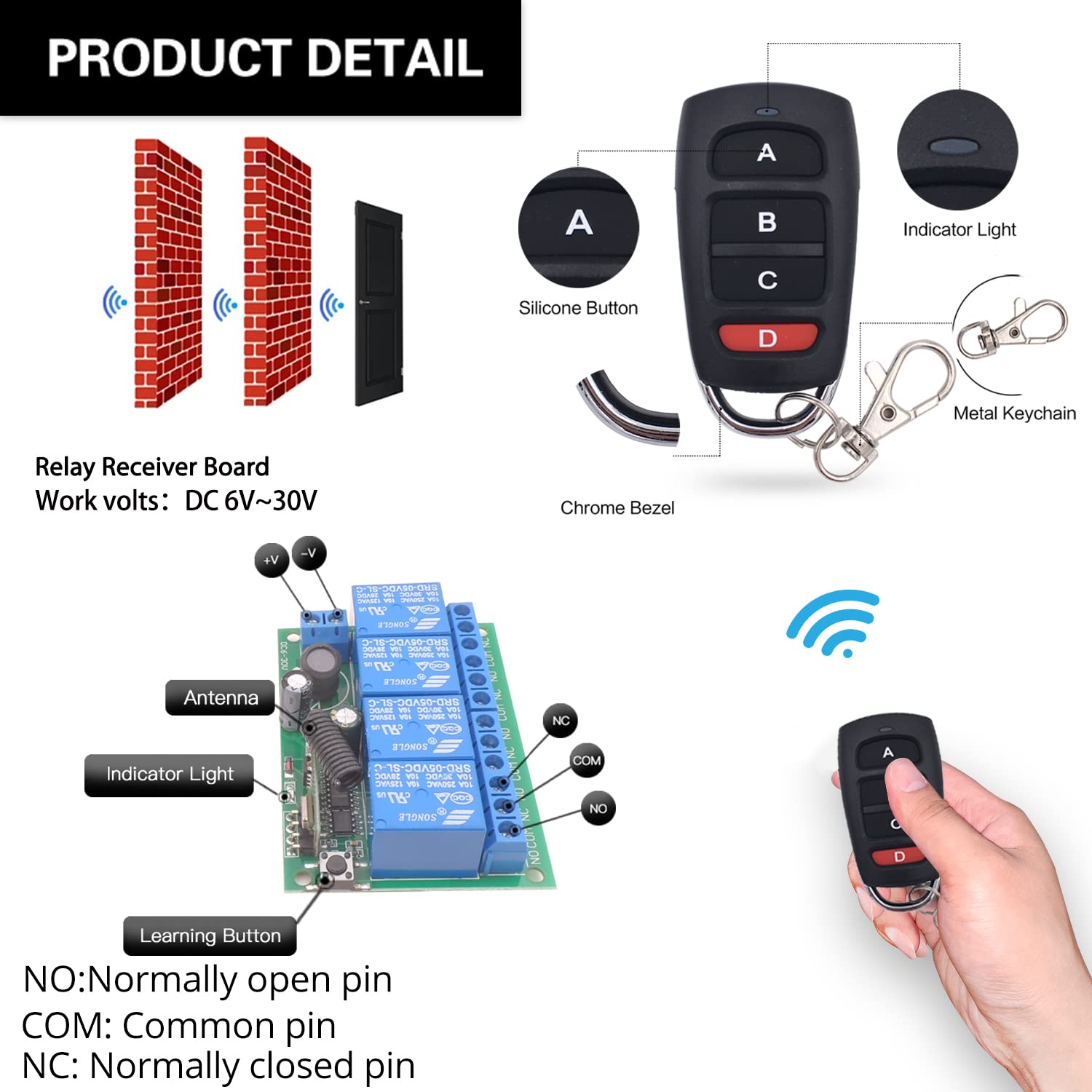
- Receiver board – 4 independent 10A relays, antenna, indicator light, learning button
- 2 x RF transmitters – silicone buttons, indicator light, metal keychain, powered by CR2032 battery (included)
- Each relay has three terminals: NO (Normally Open), COM (Common), NC (Normally Closed)
Wiring Diagram


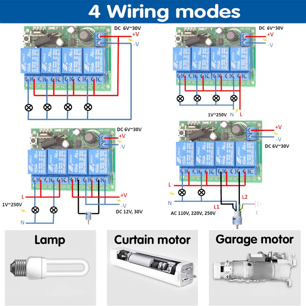
- Power input: Connect DC 6V-30V to VCC (+) and GND (-)
- Relay output (dry contacts): Four independent relays (NO/COM/NC)
- Examples: AC lamp (1V-250V), curtain motor (DC 12V, 30V), garage motor (AC 110V, 220V, 250V)
Warning
- Always disconnect power before performing any wiring or maintenance.
- Do not exceed the maximum current rating of 10A per relay.
- Ensure input voltage is within DC 6V-30V.
- Keep the device away from water, moisture, and extreme temperatures.
- If unsure about wiring, consult a qualified electrician.
- Usually the receiver and transmitter have been paired in factory. If not, reprogram them.
- Reset before you want to change the operating mode.
- After reset, all remote controls cannot work anymore.
- Replace the battery in time when the remote transmitter voltage is low.
Operating Mode
The receiver supports three operating modes. Follow the programming steps below.
Momentary Mode
Press and hold a button → relay activates (device ON)
Release the button → relay deactivates (device OFF)
How to program:
- Press the learning button on the receiver 1 time. The indicator light will illuminate.
- Press any button on the remote control. The indicator light will flash, confirming successful programming.
Toggle Mode
Press a button once → relay activates (device ON)
Press the same button again → relay deactivates (device OFF)
How to program:
- Press the learning button on the receiver 2 times. The indicator light will illuminate.
- Press any button on the remote control. The indicator light will flash, confirming successful programming.
Latched Mode
Press button A → Relay 1 turns ON (Relay 2 turns OFF)
Press button B → Relay 2 turns ON (Relay 1 turns OFF)
How to program:
- Press the learning button on the receiver 3 times. The indicator light will illuminate.
- Press button A on the remote control.
- Press button B on the remote control. The indicator light will flash, confirming successful programming.
Note: In Latched mode, one relay turns ON while another turns OFF, ensuring only one is active at a time.
Reset
To clear all programmed remote controls and reset the receiver to its default state, press the learning button 8 times. The indicator light will flash, confirming that all previous pairings have been cleared.

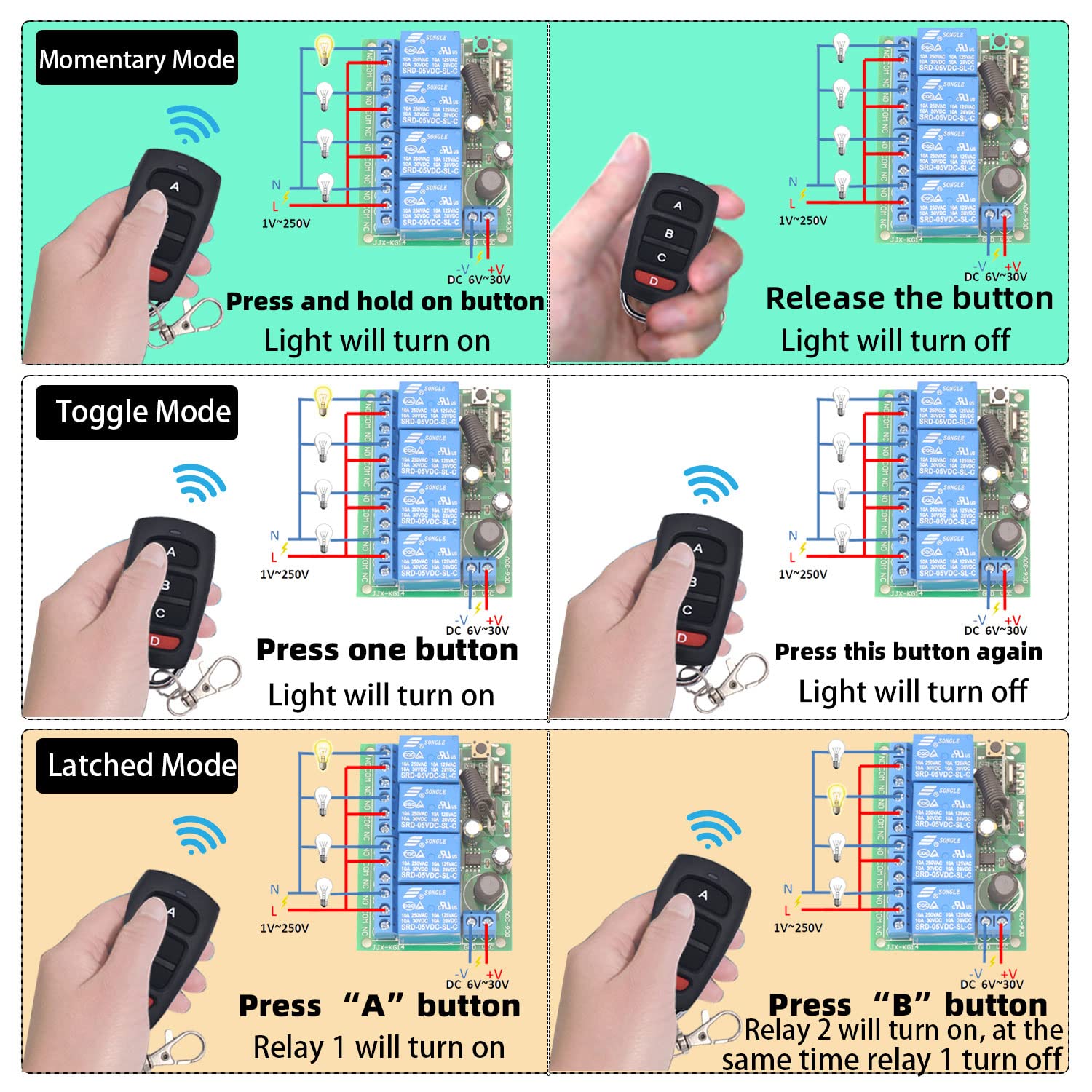
Troubleshooting
| Problem | Possible Cause | Solution |
|---|---|---|
| Remote not responding | Out of range; Low/dead battery; Receiver not powered; Remote not paired | Move closer; Replace CR2032 battery; Verify DC 6V-30V power; Re-program remote |
| Relay not activating/deactivating correctly | Incorrect wiring; Wrong operating mode; Overload | Check wiring against diagrams; Reprogram desired mode; Ensure load ≤10A |
| Accidental activation or erratic behavior | RF interference; Unintended signals | Reset receiver (press learning button 8 times); Re-program only desired remotes; Keep away from strong EMI sources |
Maintenance
- Cleaning: Wipe with a dry, soft cloth. Do not use harsh chemicals or abrasive cleaners.
- Environment: Keep receiver in a dry location, away from moisture, extreme temperatures, and corrosive substances.
- Battery replacement: Replace remote CR2032 battery when range decreases or LED dims.
- Wiring: Periodically check all connections for wear, corrosion, or looseness.
- Avoid overloading: Do not exceed 10A per relay.
Contact
- WhatsApp: +86 15812381273
- Email: linktrol@icloud.com
If there is any question about the products, please contact us first. We will do our best to solve your problem. Thank you.
18 - SWITNEX DC 24V Wireless Relay Remote Control Switch User Manual
SWITNEX DC 24V Wireless Relay Remote Control Switch User Manual
| Technical Data | |
|---|---|
| Receiver Operating voltage | DC 6V ~ 30V |
| Input / output voltage | 1 ~ 250V |
| Max current | 10A |
| RF frequency | 433MHz |
| Support encoding | 1527 learning code |
| Receiving sensitivity | >97dbm |
| RF working mode | ASK superheterodyne wireless reception |
| Working temperature | -30 ~ +80 |
| Reception range | Open space is more than 50 meters |
| Quiescent current | <5 MA |
Product Detail

- NO: Normally open pin
- COM: Common pin
- NC: Normally closed pin
- Learning button on receiver – for programming modes and resetting
- Indicator LED on receiver – provides visual feedback
- Antenna on receiver – extend for better signal reception
Wiring Diagram


Warning
- Usually, the receiver and transmitter have been paired with each other in the factory. If not, you can reprogram by yourself.
- Reset before you want to change the operating mode.
- After resetting, all the remote controls cannot work anymore.
- Replace the battery in time when the remote transmitter voltage is low to get stronger signal transmission.
- Slightly stretch the antenna on the receiver for better signal reception.
- The remote transmitter needs to have 3 or more buttons if you want to set up in latched mode.
- The output type is passive output / potential-free contacts.
Operating Mode
Momentary Mode
Press and hold button A → relay 1 turns on
Release button A → relay 1 turns off
How to program:
- Press the learning button on the receiver 1 time. The indicator LED will light down.
- Press button A on the remote transmitter. The indicator LED will flash several times and then light down.
- Press button B on the remote transmitter. The indicator LED will flash several times and then light up. Succeed.
Toggle Mode
Press button A → relay 1 turns on
Press button A again → relay 1 turns off
How to program:
- Press the learning button on the receiver 2 times. The indicator LED will light down.
- Press button A on the remote transmitter. The indicator LED will flash several times and then light down.
- Press button B on the remote transmitter. The indicator LED will flash several times and then light up. Succeed.
Latched Mode
Press button A → relay 1 turns on
Press button B → relay 2 turns on, and relay 1 turns off at the same time
How to program:
- Press the learning button on the receiver 3 times. The indicator LED will light down.
- Press button A on the remote transmitter. The indicator LED will flash several times and then light down.
- Press button B on the remote transmitter. The indicator LED will flash several times and then light up. Succeed.


Reset
Press the learning button on the receiver 8 times. The indicator LED will flash several times and then light up. Succeed.
Troubleshooting
If the receiver and transmitter cannot operate normally, try the following steps:
- Check if the battery’s power is used up. The indicator LED on the remote transmitter does not light up or is dimly lit.
- Check if your receiver is wired correctly. It is important to make sure the wiring is correct.
- Reprogram the receiver and transmitter. Usually this can solve many problems.
- If the problem remains, please contact us in time. We will do our best to solve your problem.
Contact
- WhatsApp: +86 15812381273
- Email: linktrol@icloud.com
If there is any question about the products, please contact us first. We will do our best to solve your problem. Thank you.
19 - SWITNEX Radio Frequency Light Remote Control Switch User Manual
SWITNEX Radio Frequency Light Remote Control Switch User Manual
| Technical Data | |
|---|---|
| Receiver Working Voltage | AC 85V~240V |
| Quiescent Current | <5mA |
| Max Current | 10A |
| Max Wattage | 1500 Watts |
| RF frequency | 433MHz |
| Working temperature | -30°C ~ +80°C |
| Receiving Sensitivity | >97dbm |
| Storage remote controls | Up to 20 pieces |
| Support encoding | 1527 Learning code |
| RF Operating mode | ASK superheterodyne wireless reception |
| Receiving range (open space) | >50 meters |
| Pin Configuration | N / L |
| Remote operating mode | Momentary / Toggle / Latched |
| Transmitter Battery | 2x CR2016 (included) |
| Maximum Switching Current | 10 Amps |
| Receiver dimensions | 70 x 38 x 21 mm |
Product Detail

- Receiver module – with protective casing, learning button, indicator LED, antenna
- 2 x Transmitters – key fob style, each with CR2016 batteries included
- NO: Normally open pin (relay output)
- COM: Common pin
- NC: Normally closed pin
- Power input terminals: N (Neutral), L (Live) – AC 85V-240V
Wiring Diagram

- Connect power source (AC 85V-240V) to L and N input terminals
- Connect appliance (e.g., lamp) to output terminals (L and N)
- Relay contacts (NO, COM, NC) are potential-free
Warning
- Always disconnect power before performing any wiring or maintenance.
- Do not exceed the maximum load of 1500W or 10A.
- Ensure the voltage matches AC 85V-240V.
- Keep device away from moisture and extreme temperatures.
- Keep remote controls out of reach of children.
- Usually the receiver and transmitter have been paired in factory. If not, reprogram them.
- Reset before you want to change the operating mode.
- After reset, all remote controls cannot work anymore.
- Replace the battery in time when the remote transmitter voltage is low.
Operating Mode
The product is typically pre-set to Toggle Mode from the factory. Follow the steps below to change modes.
Momentary Mode
Press and hold a button → relay activates (device ON)
Release the button → relay deactivates (device OFF)
How to program:
- Press the learning button on the receiver 1 time.
- Wait approximately 3 seconds.
- Press any button on the transmitter. The indicator light will flash. Succeed.
Toggle Mode
Press a button once → relay activates (device ON)
Press the same button again → relay deactivates (device OFF)
How to program:
- Press the learning button on the receiver 2 times.
- Wait approximately 3 seconds.
- Press any button on the transmitter. The indicator light will flash. Succeed.
Latched Mode
Press ON button → relay activates (device ON)
Press OFF button → relay deactivates (device OFF)
How to program:
- Press the learning button on the receiver 3 times.
- Wait approximately 3 seconds.
- Press the desired ON button on the transmitter.
- Press the desired OFF button on the transmitter. The indicator light will flash. Succeed.
Reset
To clear all paired transmitters from the receiver’s memory, press the learning button 8 times consecutively. The reset is successful. After reset, all previously paired remotes will no longer function.


Troubleshooting
If the receiver and transmitter cannot operate normally, try the following steps:
- Device not responding: Check power supply (AC 85V-240V). Ensure remote batteries are not depleted. Verify remote is correctly programmed. Check for obstructions or excessive distance.
- Incorrect mode operation: Reset the receiver (press learning button 8 times) and reprogram the desired mode.
- Weak range: Extend the receiver antenna. Replace remote batteries. Minimize interference from other RF devices.
Maintenance
- Battery replacement (transmitter): Replace with 2x CR2016 batteries when range decreases or LED is dim. Ensure correct polarity.
- Cleaning: Wipe the receiver and remote controls with a soft, dry cloth. Do not use liquid cleaners or solvents.
- Relay durability: Rated for over 400,000 operations; transmitter buttons for over 500,000 clicks.
Contact
- WhatsApp: +86 15812381273
- Email: linktrol@icloud.com
If there is any question about the products, please contact us first. We will do our best to solve your problem. Thank you.
20 - SWITNEX RF 433MHz Wireless Light Switch System User Manual
SWITNEX RF 433MHz Wireless Light Switch System User Manual
| Technical Data | |
|---|---|
| Model Number | 750828381477 |
| Product Dimensions (Switch) | 8.8 x 8.8 x 2.3 cm |
| Product Weight (Switch) | 60 grams |
| Receiver Dimensions | 4.7 x 4.2 x 2.3 cm |
| Operating Voltage (Receiver) | AC 85V ~ 250V |
| Current Rating (Receiver) | 10 A |
| RF frequency | 433 MHz |
| Learning Code | EV1527 |
| Switch Battery | 1 x 12V 27A (included) |
| Switch Lifespan | Over 500,000 clicks |
| Receiver Relay Lifespan | Over 400,000 uses |
| Material | Plastic |
| Switch Type | Push Button |
| Terminal Type | Screw |
| Country of Origin | China |
Product Detail

- Receiver terminals: Input L / Input N (from power source), Output L / Output N (to appliance)
- Learning button on receiver – for pairing and resetting
- Indicator light on receiver – provides visual feedback during programming
- Antenna on receiver – can be extended for stronger signal
Wiring Diagram

Warning
- Always disconnect power at the circuit breaker before installing or servicing any electrical components.
- Installation should be performed by a qualified electrician or in accordance with local electrical codes.
- Do not exceed the maximum load rating of 10A for the receiver.
- Ensure all wire connections are secure to prevent electrical hazards.
- Keep the device away from water and extreme temperatures.
- The wireless switch requires no wiring – can be mounted with adhesive tape or screws.
Operating Mode
Toggle Mode
Press the button on the wireless switch → light turns ON
Press the same button again → light turns OFF
How to program (pairing):
- Ensure the receiver is powered on.
- Press the learning button on the receiver 2 times. Wait 3 seconds. The indicator light on the receiver will blink.
- Press the button on the wireless switch. Wait 3 seconds. The indicator light will stop blinking, indicating successful pairing.
Multi-Control Scenarios
- Multiple switches control one lamp: Pair up to 10 wireless switches with a single receiver (3-way switch setup).
- One switch controls multiple lamps: Pair a single wireless switch with multiple receivers for simultaneous control.

Reset
Press the learning button on the receiver 8 times. Wait 3 seconds. The indicator light will blink rapidly and then turn off, indicating that all paired devices have been cleared.
Troubleshooting
If the receiver and transmitter cannot operate normally, try the following steps:
- Weak signal reception: Extend the antenna on the receiver. Ensure the switch battery is not depleted. Verify the switch and receiver are within effective range (up to 50 meters in open areas).
- Switch not responding: Check the 12V 27A battery. Replace if necessary. Re-pair the switch with the receiver (see Operating Mode > How to program).
- Receiver not toggling: Confirm wiring is correct (Input L/N to power source, Output L/N to appliance). Ensure the load does not exceed 10A.
- Reset receiver (press learning button 8 times) to clear all pairings, then re-pair.
Maintenance
- Battery replacement (wireless switch): The 12V 27A battery typically lasts about 5 years. Carefully open the switch casing, remove the old battery, insert a new one with correct polarity, and close securely.
- Cleaning: Wipe the switch and receiver with a soft, dry cloth. Do not use abrasive cleaners or immerse in water.
Contact
- Email: linktrol@icloud.com
- WhatsApp: +86 15812381273 Refer to the product packaging or the retailer’s website for customer support contact information.
If there is any question about the products, please contact us first. We will do our best to solve your problem. Thank you.
21 - SWITNEX AC85-250V RF Wireless Remote Control Switch User Manual
SWITNEX AC85-250V RF Wireless Remote Control Switch User Manual
| Technical Data | |
|---|---|
| Brand | SWITNEX |
| Model Number | 2 Boutons |
| Connections | Wireless |
| Terminal Type | Clamp |
| Compatible Devices | AC |
| Remote Battery Type | Lithium Manganese Dioxide (CR2032) |
| Operating Modes | Momentary, Toggle, Latched |
| Max Power | 2500 Watts |
| Working Voltage | AC 85V-250V |
| Output Voltage | 1V-250V |
| Current Rating | 10A |
| Contact Material | Copper |
| Contact Type | Normally Open (NO) |
| Mounting Type | Wall Mount |
| Frequency | 433MHz |
| Code Type | 1527 Learning Code or 2262 Fixed Code |
Product Detail

- 1 x SWITNEX 433MHz RF Relay Receiver Module – with protective casing
- 2 x 2-Button Remote Controls – each with buttons A and B, powered by CR2032 battery
- Terminals: N (Neutral input), L (Live input), NO (Normally Open), COM (Common), NC (Normally Closed)
- Learning button on receiver – for programming modes and resetting
- Indicator light on receiver – provides visual feedback
Wiring Diagram


- N terminal: Neutral wire input (AC power source)
- L terminal: Live wire input (AC power source)
- NO/COM/NC terminals: Output connections to device
- AC device: Connect power source to L/N; device to COM and NO
- DC device: Connect AC power to L/N; DC power supply output to COM/NO (observe polarity)
- AC motor (rolling shutters): Connect motor Up wire to one NO, Down wire to another NO, common wire to corresponding COM
- DC motor: Connect DC power supply output to COM terminals; motor positive/negative to NO terminals
Warning
- Always disconnect power before installing or servicing the device. Improper wiring can lead to electric shock or fire.
- Installation should be performed by a qualified electrician or knowledgeable individual.
- Ensure the operating voltage of your device matches the receiver specifications (AC 85V-250V).
- Do not exceed the maximum current rating of 10A or power rating of 2500W.
- Install the receiver in a dry, well-ventilated area, away from direct sunlight, high temperatures, and corrosive environments.
- Keep remote controls and the receiver out of reach of children.
Operating Mode
Momentary Mode
Press and hold a remote button → relay activated
Release the button → relay deactivated
How to program:
- Press the learning button on the receiver 1 time. The indicator light will flash.
- Press button A on the remote control. The indicator light will flash, confirming successful pairing.
Toggle Mode
Press a remote button once → relay activates and stays on
Press the same button again → relay deactivates
How to program:
- Press the learning button on the receiver 2 times. The indicator light will flash.
- Press button A on the remote control. The indicator light will flash, confirming successful pairing.
Latched Mode
Press button A → Relay 1 activates
Press button B → Relay 2 activates, and Relay 1 deactivates simultaneously
How to program:
- Press the learning button on the receiver 3 times. The indicator light will flash.
- Press button A on the remote control (program Relay 1).
- Press button B on the remote control (program Relay 2). The indicator light will flash, confirming successful pairing.


Reset
To clear all programmed remote controls from the receiver, press the learning button 8 times consecutively. The indicator light will flash rapidly and then turn off, indicating that all stored codes have been cleared. After reset, reprogram your remotes following the steps above.

Troubleshooting
| Problem | Possible Cause | Solution |
|---|---|---|
| Relay clicks but device does not activate | Incorrect wiring between output terminals (NO, COM, NC) and device; Device malfunction | Check wiring connections; Test device by powering directly |
| Device not responding to remote | No power to receiver; Remote battery low/dead; Remote not programmed; Receiver reset | Check power supply; Replace CR2032 battery; Re-program remote; Reset and re-pair if needed |
| Reduced remote control range | Low remote battery; Environmental interference; Obstructions | Replace CR2032 battery; Minimize interference; Ensure clear line of sight |
Maintenance
- Keep the receiver module and remote controls clean and dry.
- Avoid exposing them to extreme temperatures, humidity, or corrosive substances.
- Do not attempt to repair internal components yourself; contact qualified personnel if service is required.
- Replace remote battery when range decreases or LED dims (use CR2032 lithium cell, positive side up).
Contact
- Email: linktrol@icloud.com
- WhatsApp: +86 15812381273
If there is any question about the products, please contact us first. We will do our best to solve your problem. Thank you.
22 - SWITNEX 2204 Universal Wireless Remote Control Instruction Manual
SWITNEX 2204 Universal Wireless Remote Control Instruction Manual
| Technical Data | |
|---|---|
| Working voltage | AC 85V~250V |
| Input/output voltage | 1~250V |
| Output Type | Passive output |
| Quiescent Current | <5MA |
| Max current | 10A |
| RF frequency | 433MHz |
| Working temperature | -30~+80 |
| Receiving Sensitivity | >97dbm |
| Amount of storage remote controls | 20 pieces |
| Support encoding | 1527 Leaning code、2262 fixed code |
| RF Operating mode | ASK superheterodyne wireless reception |
| Receiving range | Open space is more than 50 meters |
| Remote operating mode | Momentary Mode / Toggle Mode / Latched Mode |
Product Detail

- NO: Normally open pin
- COM: Common pin
- NC: Normally closed pin
Wiring Diagram

Warning
- Usually the receiver and transmitter have been paired with each other in factory. If not, please reprogram them.
- Reset before you want to change the operating mode.
- After reset, all the remote controls cannot work anymore.
- Replace the battery in time when the remote transmitter voltage is low to get stronger signal transmission.
- Slightly stretch the antenna on the receiver for better signal reception.
- The remote transmitter needs to have 5 or more buttons if you want to set up in latched mode.
- The output type is passive output / potential-free contacts.
Operating Mode
Momentary Mode
Press and hold button “A” → relay “1” turns on
Release button “A” → relay “1” turns off
How to program:
- Press the learning button (on the receiver) 1 time. The indicator LED on the receiver will light up.
- Press button “A” on the remote transmitter. The indicator LED on the receiver will flash several times and then turn off. Succeed.
Toggle Mode
Press button “A” → relay “1” turns on
Press button “A” again → relay “1” turns off
How to program:
- Press the learning button (on the receiver) 2 times. The indicator LED on the receiver will light up.
- Press button “A” on the remote transmitter. The indicator LED on the receiver will flash several times and then turn off. Succeed.
Latched Mode
Press button “A” → relay “1” turns on
Press button “B” → relay “2” turns on, and relay “1” turns off at the same time
How to program:
- Press the learning button (on the receiver) 3 times. The indicator LED on the receiver will light up.
- Press button “A” on the remote transmitter. The indicator LED on the receiver will flash several times and then turn off. Succeed.

Reset
Press the learning button (on the receiver) 8 times. The indicator LED on the receiver will flash several times and then turn off. Succeed.
Troubleshooting
If the receiver and transmitter cannot operate normally, try the following steps:
- Check if battery power is used up. The indicator LED on the remote transmitter does not light up or is dimly lit.
- Check if your receiver is wired correctly. Make sure the wiring is correct.
- Reprogram the receiver and transmitter. Usually this can solve many problems.
- If the problem still remains, please contact us.
Contact
- Email: linktrol@icloud.com
- WhatsApp: +86 15812381273
If there is any question about the products, please contact us first. We will do our best to solve your problem. Thank you.
23 - SWITNEX DC12-48V 433MHz Wireless Remote Control Switch User Manual
SWITNEX DC12-48V 433MHz Wireless Remote Control Switch User Manual
| Technical Data | |
|---|---|
| Operating Voltage | DC 12V ~ 48V |
| Max Current Rating | 40 Amps |
| RF frequency | 433MHz |
| Control Range | Up to 50 meters (162 feet) without obstacles |
| Operating Modes | Momentary, Toggle, Latched (default: Latched) |
| Transmitter Storage | Receiver can store up to 20 transmitters |
| Receiver Dimensions | 2.56 x 2.36 x 1.18 inches (65x58x30mm) |
| Transmitter Dimensions | 2.3 x 1.2 x 0.4 inches (60x30x14mm) |
| Remote Control Battery | 1 x CR2032 (included) |
Product Detail

- Receiver unit – Features 40A relay, input/output terminals (DC Input / DC Output), antenna, indicator light, learning button
- 2 x Remote keyfob transmitters – Each with ‘ON’ and ‘OFF’ buttons, indicator light, metal keychain for portability
- 433MHz RF signal – Can pass through walls, floors, doors
- Output Type: Potential-free contacts / passive output (relay)
Wiring Diagram


- Connect DC power source (12V-75V) to receiver’s ‘DC Input’ terminals
- Connect electrical appliance to receiver’s ‘DC Output’ terminals (max 40A)
Warning
- Ensure power is disconnected before wiring the receiver. All wiring should be performed by a qualified electrician or in accordance with local electrical codes.
- Do not exceed the maximum voltage (DC 75V) or current rating (40A).
- Avoid exposing the device to extreme temperatures, humidity, or corrosive environments.
- While designed for stable performance, strong electromagnetic interference may affect signal reception.
- Reset before you want to change the operating mode.
- After reset, all the remote controls cannot work anymore.
- Replace the battery in time when the remote transmitter voltage is low.
- Slightly stretch the antenna on the receiver for better signal reception.
Operating Mode
The product is typically pre-set to Latched Mode. To re-pair or change modes, follow the steps below.
Latched Mode (Default)
Press ON button → relay turns on (appliance ON)
Press OFF button → relay turns off
How to program:
- Press the learning button on the receiver 3 times. The indicator light will flash, indicating learning mode for Latched Mode.
- Press the ON button on the remote control. The receiver’s indicator light will flash once, then turn off.
- Press the OFF button on the remote control. The receiver’s indicator light will flash once, then turn off. Succeed.
Momentary Mode (Advanced)
Press and hold a button → relay turns on
Release the button → relay turns off
How to program: (Refer to manufacturer’s advanced documentation – typically press learning button 1 time then press remote button)
Toggle Mode (Advanced)
Press a button once → relay turns on
Press the same button again → relay turns off
How to program: (Refer to manufacturer’s advanced documentation – typically press learning button 2 times then press remote button)
Reset
To clear all paired transmitters from the receiver’s memory, press the learning button 8 times. The receiver’s indicator light will flash rapidly, then turn off, indicating all paired remotes have been cleared.

Troubleshooting
| Problem | Possible Cause | Solution |
|---|---|---|
| Device does not respond to remote | Receiver not powered; Remote battery depleted; Remote not paired; Obstructions | Check power and wiring; Replace CR2032 battery; Re-pair remote (see Latched Mode programming); Ensure within 50m range |
| Device turns ON but immediately OFF when button released | Receiver might be in Momentary mode | Re-pair remote following Latched Mode instructions (press learning button 3 times) |
| Reduced remote control range | Low battery; Antenna not extended; Obstructions; Electromagnetic interference | Replace battery; Extend antenna; Minimize obstacles; Avoid interference sources |
| Receiver indicator light not working | No power to receiver; Incorrect wiring | Check power supply; Verify wiring is correct and secure |
Applications
- Lighting: Indoor/outdoor lights, LED spotlights, chandeliers
- Pumps: Water pumps for irrigation, fountains, pools
- Household appliances: Electric fans, coffee makers
- Security systems: Wireless security alarms, ventilation devices
- DIY projects: Custom remote control solutions
Maintenance
- Cleaning: Use a soft, dry cloth to clean the receiver and remote controls. Do not use abrasive cleaners or solvents.
- Battery replacement: The remote uses a CR2032 battery. Replace when indicator light dims or range decreases. Ensure correct polarity.
- Environmental protection: Keep the receiver in a dry, well-ventilated area, away from direct sunlight, excessive heat, and moisture.
- Antenna: Ensure the receiver’s antenna is extended for optimal signal reception.
Contact
- WhatsApp: +86 15812381273
- Email: linktrol@icloud.com
If there is any question about the products, please contact us first. We will do our best to solve your problem. Thank you.
24 - SWITNEX AC 110V-240V Wireless Remote Control Light Switch (Model: B0FKS38W6K) User Manual
SWITNEX AC 110V-240V Wireless Remote Control Light Switch (Model: B0FKS38W6K) User Manual
| Technical Data | |
|---|---|
| Operation Mode | ON-OFF |
| Current Rating | 10 Amps |
| Operating Voltage | AC 90V-250V (110V, 120V, 220V, 240V compatible) |
| Max Load (Resistive) | 1500W |
| Contact Type | Normally Open |
| Connector Type | Crimp |
| Terminal | Screw |
| Receiver Dimensions (L x W x H) | 65 x 36 x 23 mm (2.56 x 1.42 x 0.91 inches) |
| Transmitter Dimensions (L x W x H) | 115 x 70 x 15 mm (4.53 x 2.76 x 0.59 inches) |
| Circuit Type | 1-way |
| Contact Material | Plastic |
| RF frequency | 433MHz |
| Control Distance (Open area) | Up to 30 meters (100 feet) |
| Control Distance (Through walls/doors) | 30-55 meters (100-180 feet) |
| Transmitter Battery | 1 x AAA 12V (included) |
Product Detail

- RF Relay Receiver – compact unit (65x36x23mm), input/output terminals (L and N)
- 2 x Remote Control Transmitters – keyfob style with ON/OFF buttons
- 1 x AAA 12V battery – pre-installed in transmitter
- Double-sided tape – for transmitter mounting
- Screws – for transmitter mounting
- Learning button on receiver – for programming modes and resetting
- Indicator light on receiver – provides visual feedback
Wiring Diagram

- Input: Connect AC 90V-250V power supply to input terminals (Live ‘L’ and Neutral ‘N’)
- Output: Connect device (e.g., lamp, fan) to output terminals
- Scenario A: Receiver in series with Live (L) wire
- Scenario B: Receiver in series with Neutral (N) wire
Warning
- Always disconnect power at the circuit breaker before installing or servicing the receiver.
- Installation should be performed by a qualified electrician or in accordance with local electrical codes.
- Do not exceed the maximum load capacity of 1500W (10A resistive load).
- Ensure the operating voltage (AC 90V-250V) is compatible with your electrical system.
- Keep the device away from water and high humidity environments.
- Do not attempt to disassemble or modify the device.
- Usually the receiver and transmitter have been paired in factory. If not, reprogram them.
- Reset before you want to change the operating mode.
- After reset, all remote controls cannot work anymore.
- Replace the battery in time when the remote transmitter voltage is low.
Operating Mode
The product is pre-set to Latched Mode by default. Follow the programming steps below to change modes.
Momentary Mode
Press and hold a button → device turns ON
Release the button → device turns OFF
How to program:
- Press the learning button on the receiver 4 time. The indicator light will flash.
- Press the desired button on the transmitter. The indicator light will flash to confirm.
Toggle Mode
Press a button once → device turns ON
Press the same button again → device turns OFF
How to program:
- Press the learning button on the receiver 2 times. The indicator light will flash.
- Press the desired button on the transmitter. The indicator light will flash to confirm.
Latched Mode
Press ON button → device turns ON
Press OFF button → device turns OFF
How to program:
- Press the learning button on the receiver 3 times. The indicator light will flash.
- Press the ON button on the transmitter. The indicator light will flash.
- Press the OFF button on the transmitter. The indicator light will flash to confirm.
Reset
To clear all paired transmitters from the receiver’s memory, press the learning button 8 times. The indicator light will flash rapidly and then turn off, indicating all stored data has been cleared. After reset, re-pair transmitters as needed.
Transmitter Installation
- Fixed mode: Mount to wall or flat surface using double-sided tape (non-permanent) or screws (secure). Open casing to access mounting holes and battery compartment.
- Portable mode: Use as a handheld remote control from anywhere within range.

Troubleshooting
If the receiver and transmitter cannot operate normally, try the following steps:
- Device not responding: Check receiver wiring and power. Ensure transmitter battery is functional (replace if needed). Re-pair transmitter and receiver. Verify connected device works when directly powered.
- Reduced control range: Remove metallic obstructions. Do not place receiver inside metal enclosures. Avoid strong RF interference from other devices.
- Transmitter not working: Replace AAA 12V battery. Ensure correct polarity.
Maintenance
- Cleaning: Wipe devices with a soft, dry cloth. Do not use harsh chemicals or abrasive cleaners.
- Battery replacement: The transmitter uses a 12V AAA battery. Open casing carefully, replace battery with correct polarity.
- Storage: Store in a cool, dry place away from direct sunlight and extreme temperatures.
Contact
- WhatsApp: +86 15812381273
- Email: linktrol@icloud.com
If there is any question about the products, please contact us first. We will do our best to solve your problem. Thank you.
25 - DieseRC Wireless Remote Control Switch System User Manual
DieseRC Wireless Remote Control Switch System User Manual
| Technical Data | |
|---|---|
| Brand | DieseRC |
| Model | RX26 |
| Operating Voltage (Receiver) | DC 3.6V ~ 30V |
| Max Load Current | 2A |
| RF frequency | 433MHz |
| Encoding Type | EV1527 Learning Code |
| Receiver Dimensions (L x W x T) | 31mm x 15mm x 4mm (approx. 1.2 x 0.6 x 0.2 inches) |
| Transmitter Dimensions (L x W x T) | 62mm x 30mm x 13mm (approx. 2.4 x 1.2 x 0.5 inches) |
| Transmitter Battery | 2x CR2016 (included) |
| Max Supported Transmitters (per receiver) | 15 pieces |
| Control Distance (open area) | Up to 40 meters |
| Operating Modes | Momentary, Toggle, Latched, Delay |
| |
Product Detail

- 2 x Receiver modules – mini-sized (31x15x4mm) with coiled antenna, learning button, indicator light
- 2 x Transmitters – key fob style with buttons ‘A’ and ‘B’, powered by 2x CR2016 batteries (included)
- Receiver terminals: IN+ (positive input), IN- (negative input), OUT+ (positive output), OUT- (negative output)
Wiring Diagram

- Power input: Connect DC 3.6V-30V to IN+ (positive) and IN- (negative)
- Device output: Connect target device (e.g., LED light, electric lock) to OUT+ and OUT-
- Maximum load current: 2A
Warning
- Ensure the power supply voltage matches the receiver’s specified range (DC 3.6V-30V).
- Do not exceed the maximum load current of 2A.
- Disconnect power before performing any wiring or maintenance.
- Keep the device away from water and high humidity environments.
- Do not attempt to disassemble or modify the device.
- Usually the receiver and transmitter have been paired in factory. If not, reprogram them.
- Reset before you want to change the operating mode.
- After reset, all remote controls cannot work anymore.
- Replace the battery in time when the remote transmitter voltage is low.
Operating Mode
The default mode is Latched Mode. Follow the programming steps below to change modes.
Momentary Mode
Press and hold a button → device turns ON
Release the button → device turns OFF
How to program:
- Press the learning button on the receiver 1 time. The indicator light will turn on.
- Press any button on the transmitter. The indicator light will flash and turn off. Succeed.
Toggle Mode
Press a button once → device turns ON
Press the same button again → device turns OFF
How to program:
- Press the learning button on the receiver 2 times. The indicator light will turn on.
- Press any button on the transmitter. The indicator light will flash and turn off. Succeed.
Latched Mode
Press ON button (e.g., ‘A’) → device turns ON
Press OFF button (e.g., ‘B’) → device turns OFF
How to program:
- Press the learning button on the receiver 3 times. The indicator light will turn on.
- Press the ON button on the transmitter.
- Press the OFF button on the transmitter. The indicator light will flash and turn off. Succeed.
Delay Mode
Press a button → device turns ON and automatically turns OFF after a set delay Delay options:
- Press learning button 4 times: 5-second delay
- Press learning button 5 times: 10-second delay
- Press learning button 6 times: 15-second delay
- Press learning button 7 times: 20-second delay How to program:
- Press the learning button the desired number of times (4, 5, 6, or 7). The indicator light will turn on.
- Press any button on the transmitter. The indicator light will flash and turn off. Succeed.
Reset
To clear all paired transmitters from a receiver, press the learning button 8 times. The indicator light will flash 8 times and then turn off, indicating all stored transmitters have been cleared.


Troubleshooting
If the receiver and transmitter cannot operate normally, try the following steps:
- Device not responding: Check wiring and power (indicator light should flash). Ensure transmitter batteries are not depleted. Verify correct pairing. Check distance and obstacles.
- Intermittent operation: Ensure antenna is not obstructed. Minimize RF interference.
- Device turns ON/OFF unexpectedly: May indicate interference or incorrect mode. Re-pair and select correct mode.
- Receiver module gets hot: Connected device current exceeds 2A maximum load. Reduce load.
Maintenance
- Battery replacement (transmitter): Replace with 2x CR2016 batteries when range decreases. Open casing, replace with correct polarity.
- General care: Keep dry and away from extreme temperatures. Avoid dropping. Clean with soft, dry cloth. Do not use harsh chemicals.
Contact
- WhatsApp: +86 15812381273
- Email: linktrol@icloud.com
If there is any question about the products, please contact us first. We will do our best to solve your problem. Thank you.
26 - SWITNEX 2-Channel Wireless Relay Remote Control Switch User Manual
SWITNEX 2-Channel Wireless Relay Remote Control Switch User Manual
| Technical Data | |
|---|---|
| Model | 2 Channels Wireless Relay Remote Control Switch |
| Input Voltage | DC 5V-30V |
| Max Load Current | 10 Amps per channel |
| RF frequency | 433MHz |
| Output Style | Passive Output (Dry Contacts) |
| Contact Type | Normally Open (NO), Common (COM), Normally Closed (NC) |
| Operating Modes | Momentary, Toggle, Latched |
| Transmitter Battery | A27 (Alkaline, included) |
| Receiver Dimensions | Approx. 95mm x 56mm x 24mm (3.7 x 2.2 x 0.9 inches) |
| Weight | Approx. 5.6 ounces |
Product Detail

- Receiver board – operates on DC 5V-30V, includes indicator light, learning button, antenna
- 2 x Keyfob transmitters – metal buttons, chrome bezel, sliding closure to prevent accidental presses, buttons A and B
- Terminal block: Large screw ports for easy wiring
- Relay 1 terminals: NO1, COM1, NC1
- Relay 2 terminals: NO2, COM2, NC2
- Power terminals: VIN (positive), GND (negative)
Wiring Diagram

- VIN: Connect DC 5V-30V positive
- GND: Connect DC 5V-30V negative
- NO/COM/NC: Dry contacts for each relay (passive output)
- Connect device power circuit through relay contacts (e.g., power source to COM, device to NO for normally off)
Warning
- Always disconnect power before performing any wiring or maintenance.
- Ensure input voltage is within DC 5V-30V and load current does not exceed 10A per channel.
- Do not expose the device to moisture. Remote controls are not waterproof.
- Keep out of reach of children.
- Usually the receiver and transmitter have been paired in factory. If not, reprogram them.
- Reset before you want to change the operating mode.
- After reset, all remote controls cannot work anymore.
- Replace the battery in time when the remote transmitter voltage is low.
Operating Mode
The product is typically pre-programmed in Toggle Mode. Follow the steps below to change modes.
Momentary Mode
Press and hold a button → relay activates
Release the button → relay deactivates
How to program:
- Press the learning button on the receiver 1 time. The indicator light will turn on.
- Press button A on the remote control. The indicator light will flash once.
- Press button B on the remote control. The indicator light will flash once. Succeed.
Toggle Mode
Press a button once → relay activates
Press the same button again → relay deactivates
How to program:
- Press the learning button on the receiver 2 times. The indicator light will turn on.
- Press button A on the remote control. The indicator light will flash once.
- Press button B on the remote control. The indicator light will flash once. Succeed.
Latched Mode
Press button A → Relay 1 activates, Relay 2 deactivates
Press button B → Relay 2 activates, Relay 1 deactivates
How to program:
- Press the learning button on the receiver 3 times. The indicator light will turn on.
- Press button A on the remote control. The indicator light will flash once.
- Press button B on the remote control. The indicator light will flash once. Succeed.
Reset
To clear all paired remote controls from the receiver’s memory, press the learning button 8 times consecutively. The indicator light will flash several times and then turn off, indicating all paired remotes have been cleared.


Troubleshooting
If the receiver and transmitter cannot operate normally, try the following steps:
- Receiver not responding to remote: Ensure receiver is powered correctly (DC 5V-30V). Check remote battery (A27). Verify remote is paired. Clear and re-pair if unsure. Minimize RF interference or obstacles.
- Receiver not operating at 5V: Some units may require 5.5V or 6V for reliable operation. Try increasing input voltage within 30V limit.
- Remote stopped working after moisture exposure: Remote is not waterproof. Open casing, remove battery, dry completely. Replace if needed.
- Relay clicks but device does not activate: Check wiring to NO/COM/NC terminals. Ensure device has its own power supply. Verify device load does not exceed 10A.
Maintenance
- Keep receiver and remote controls in a dry environment.
- Avoid exposing remotes to moisture or direct water contact.
- Replace remote battery (A27) when range decreases or LED becomes dim.
- Ensure wiring connections remain secure over time.
Contact
- WhatsApp: +86 15812381273
- Email: linktrol@icloud.com
If there is any question about the products, please contact us first. We will do our best to solve your problem. Thank you.
27 - SWITNEX DC 12V Wireless Relay Remote Control Switch User Manual
SWITNEX DC 12V Wireless Relay Remote Control Switch User Manual
| Technical Data | |
|---|---|
| Model Number | 1204 |
| Input / Output Volts | 1V-250V |
| Work Volts | DC 12V |
| Current Rating | 10 Amps |
| RF frequency | 433MHz |
| Reception Sensitivity | >97dBm |
| Chip Code | EV1527 (Learning Code) |
| Remote Control Range | Up to 50 meters (open area) |
| Number of Relays | 4 |
| Relay Lifespan | Over 100,000 uses |
| Connector Type | Screw Terminal |
| Contact Material | Copper Alloy |
| Contact Type | Normally Closed (NC), Common (COM), Normally Open (NO) |
| Mounting Type | Surface Mount |
| Product Dimensions | 2.95 x 2.17 x 1.18 inches |
| Product Weight | 5.93 ounces |
| Batteries (Transmitters) | 2 CR2 batteries (included) |
Product Detail

- NO: Normally open pin
- COM: Common pin
- NC: Normally closed pin
Wiring Diagram

Warning
- Usually the receiver and transmitter have been paired with each other in factory. If not, please reprogram them.
- Reset before you want to change the operating mode.
- After reset, all the remote controls cannot work anymore.
- Replace the battery in time when the remote transmitter voltage is low to get stronger signal transmission.
- Slightly stretch the antenna on the receiver for better signal reception.
- Ensure power is disconnected before making any wiring connections.
- The output type is passive output / potential-free contacts.
Operating Mode
Momentary Mode
Press and hold a button → corresponding relay turns on
Release the button → relay turns off
How to program:
- Press the learning button (on the receiver) 1 time. The indicator LED on the receiver will light up.
- Press the desired button (e.g., ‘A’) on the remote transmitter. The indicator LED will flash several times and then turn off. Succeed.
Toggle Mode
Press a button → corresponding relay turns on
Press the same button again → relay turns off
How to program:
- Press the learning button (on the receiver) 2 times. The indicator LED will light up.
- Press the desired button on the remote transmitter. The indicator LED will flash several times and then turn off. Succeed.
Latched Mode
Press button ‘A’ → Relay 1 turns on (Relay 2 turns off if it was on)
Press button ‘B’ → Relay 2 turns on, and Relay 1 turns off at the same time
How to program:
- Press the learning button (on the receiver) 3 times. The indicator LED will light up.
- Press the desired button on the remote transmitter. The indicator LED will flash several times and then turn off. Succeed.
Mixed Mode
For advanced configurations (e.g., 2 momentary + 2 toggle; 2 momentary + 2 latched; 2 toggle + 2 latched), press the learning button 4, 5, or 6 times respectively, then press the corresponding remote buttons as instructed.
Reset
Press the learning button (on the receiver) 8 times. The indicator LED will flash several times and then turn off. Succeed. (All paired transmitters will be cleared.)
Troubleshooting
If the receiver and transmitter cannot operate normally, try the following steps:
- Check if battery power is used up. The indicator LED on the remote transmitter does not light up or is dimly lit. Replace with new CR2 batteries.
- Check if your receiver is wired correctly. Make sure the wiring to NC, COM, NO terminals is correct.
- Ensure the receiver is within range (up to 50 meters in open areas) and the antenna is not obstructed.
- Avoid placing the receiver near other strong RF signal sources that may cause interference.
- Reprogram the receiver and transmitter. Usually this can solve many problems.
- If the problem still remains, please contact us.
Contact
- WA: +15812381273
- Email: linktrol@icloud.com
If there is any question about the products, please contact us first. We will do our best to solve your problem. Thank you.